-
Hello,
for the just resistor method I could imagine that the current regulators for the zener influence each other.
So I would do a buffering before averaging.
with best regards
Andreas
-
The standard LTZ1000 output is already low impedance - so kind of buffered. So there is no need to add an extra buffer before combining via resistors. So just a resistor each and than followed by a capacitor to ground for filtering (just because you can at essentially no downside). After that a buffer is kind of needed.
Combining the references might need some extra care at the ground side. The layout is important here, not so much for the noise, but for stability and the TC.
If the single refs have different levels of noise, different resistors would be needed to get the lowest noise - though long time stability would prefer same resistance.
-
finally got around to finish my dual ltz reference. the board implements a slightly modified version of Andreas' circuit (to accommodate the parts I had lying around). currently, only the datasheet components are populated, though. the first picture shows an intermediate version that still lacks the buffer (lower right) and the foam around the ltz
now it's off to the lab corner for burn-in next to the LM399 reference still got to figure out what connector to use for the temperature sensors of each reference...
-
Neat build, just few points. BNCs might not be that good if you chance every last microvolt due to thermal EMFs and usually brass outer shell.
Also I'd trim pins of LTZ much shorter, almost flush to the board surface. Having them that long might cause more harm than good, as even with foam you can't avoid air drafts 100%. -
Hello,
I guess the buffer is a LT1010 type?
with best regards
Andreas
-
Neat build, just few points. BNCs might not be that good if you chance every last microvolt due to thermal EMFs and usually brass outer shell.
Also I'd trim pins of LTZ much shorter, almost flush to the board surface. Having them that long might cause more harm than good, as even with foam you can't avoid air drafts 100%.
thanks. this is for a proof of concept, hence the BNC. the last microvolt doesn't matter for this application. but I'll keep your advice in mind for the next one
I guess the buffer is a LT1010 type?
yes, it's the buffer from the appendix of AN86. -
now it's off to the lab corner for burn-in next to the LM399 reference
That's the way we catch spiders in our house (the glass) - it looks rather appropriate!
-
now it's off to the lab corner for burn-in next to the LM399 reference
That's the way we catch spiders in our house (the glass) - it looks rather appropriate!
Huh it has 8 legs!!!!
-
Paul Rako has an article on the LTZ1000:
http://electronicdesign.com/analog/what-s-all-ltz1000-stuff-anyway
He goes on to note that the LTZ1000 is pretty much the only game in town, “National/TI obsoleted the LM199, so the LTZ1000 is the only replacement in the industry that I know of. It has quite a following, too, with one guy in Europe making a very cool looking PCB layout with slots (Fig. 2).”
Doesn't Illya aka "Tin" live in Taiwan?
-
Around 2011-2013 I spotted a table of voltage references listed by Paul Rako in a magazine enumerating all known good references ... - ADI, National and LTC were listed.
A lot of ADI stuff was listed but the LTZ1000(A) from LTC was missing as high end reference ... well I wrote the man and his answer was he was only a webmaster for a certain semiconductor company - nothing more, although we knew the man from many technical webinars ... - so his selective memory was at that time not aware of the LTZ1000(A)
Times have changed since a certain semiconductor company has acquired LTC ... ?
:-)
Flinstone
And he also didn't own this equipment http://www.edn.com/electronics-blogs/designing-ideas/4311838/The-home-lab-of-Paul-Rako
I am sure that certain semiconductor company is now offering its employees a new flavor of Kool-Aid.
@TiN
 for the recognition
-
I do live in Taiwan, but originally I'm from Ukraine, which is mm, sorta Europe
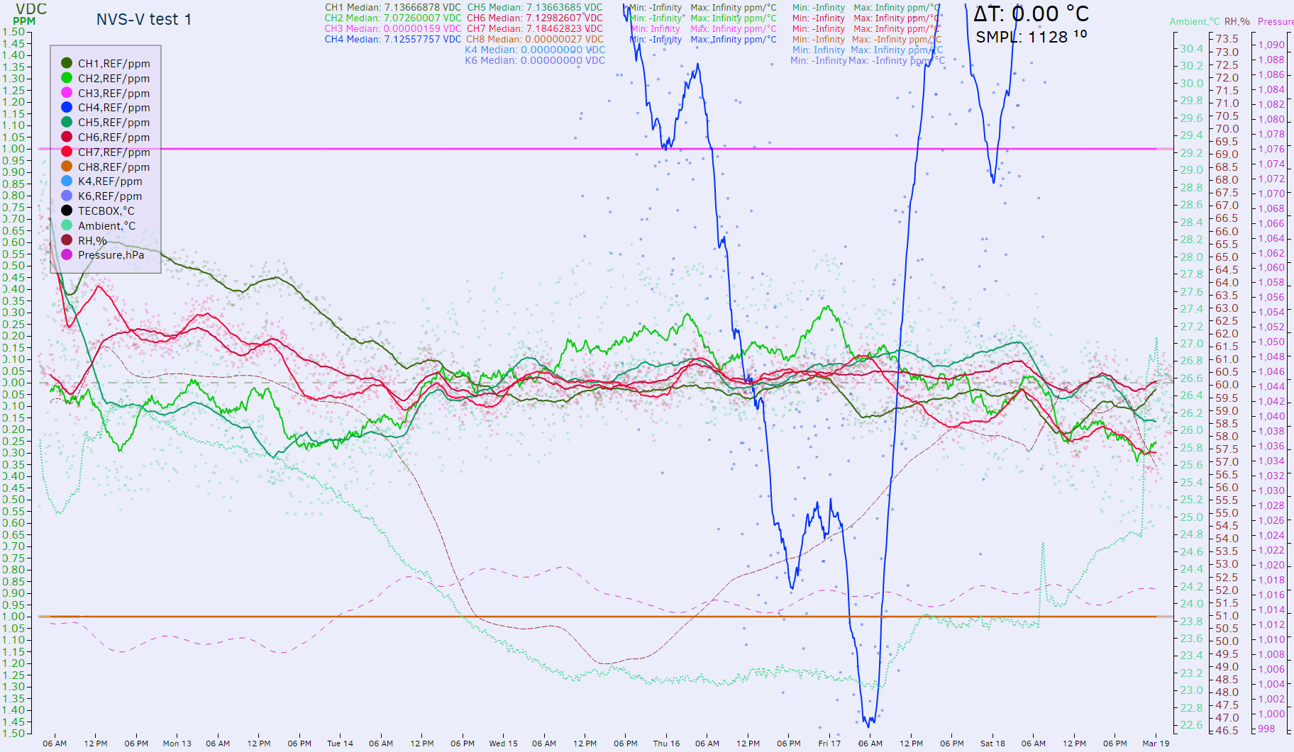
To stay on topic, I was on a business trip last week. That means gear at home is unattended. Not to waste precious digits, I hooked recent setup with Keithley 7168 scanner to bank of my LTZ1000 references, output connected to both HP 3458A's and whole thing was collecting data for a week. Whole bank powered by Keithley 2400 at +11VDC.
Both 3458A's are within 0.5ppm apart, so I just averaged reading from both of meters and presented it as final sample. All references scanned in sequence with 10 seconds soak time between switching channels. Let's see the data. My main goal on this was to see if Keithley 7168 scanner can be used for sub-ppm level accuracy measurements.
One of channel ref was not happy (ch3), it's freshly built one, so will need to check on it later. Other one, channel 4 is crazy too, going all over the joint. But five other LTZs are happily running in subppm region, which is good start.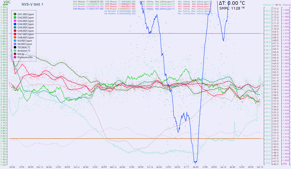
Here's averaged data with simple median of 32. CH7 bright red reference is HP A9 board, rest are my KX LTZ boards (both patched A01 PCB version and B01). I'll have to take stuff apart to give more details what is what, as some of them are LTZ1000A, other LTZ1000, and different opamps/resistors combo's too.
But hey, CH2 lime reference seem to be extra noisy, isn't it?
Reduce median filter to 2: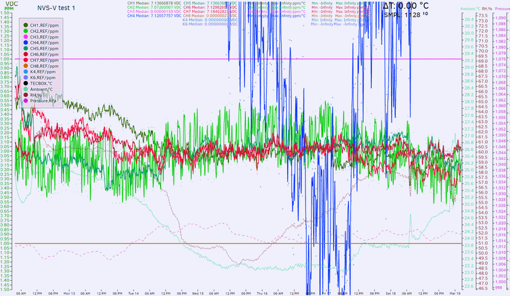
There is our good old jumper. So now this is 3rd PCB on which same chip was installed, and it's safe to confirm that jumps are coming from the flakey LTZ itself, not the related circuitry around it. As side note, this data shows that properly working LTZ1000-based refs and behaving 3458A can achieve ~0.8ppm stability in mid-term, even without battery power or controlled temperature setup. Ambient temperature on 7 day graph log vary from +26C to +23C.
I'm happy with Keithley 7168, wish I'd have two of them now.
RAW data and realtime page. -
Hei TiN, why don't you attach the little jumper to your noise meter? Just curious to see what is noise on in when not jumping.
-
I'm about to join the most prestigious club Just waiting on getting the z202 resistors from Vishay and I should have everything! I would like to practice my soldering skills before I have at it, though.
-
I'm about to join the most prestigious club
Just waiting on getting the z202 resistors from Vishay and I should have everything! I would like to practice my soldering skills before I have at it, though.
I recognize those pcb :-) -
I'm about to join the most prestigious club
Just waiting on getting the z202 resistors from Vishay and I should have everything! I would like to practice my soldering skills before I have at it, though.
I recognize those pcb :-)
Hehe Thank you so much again for sending me your extras.
-
@calmachine - please show what you did and why you did it that way.
-
@calmachine - please show what you did and why you did it that way.
Will do! Could be multiple weeks though.... I first touched base with them on March 20th with the my order, and have yet to get prices / lead time.
-
Whole bank powered by Keithley 2400 at +11VDC.
Hello Illya,
Is 11V not a bit marginal?
- depends of course also on thermal isolation and environment temperature.
at least on my cirquit with LTC2057 the dropout of the current regulator begins shortly after UBat falls below 11 V.
With best regards
Andreas
Edit: sorry was a wrong picture. now corrected.
Red: voltage over 120R
green: supply voltage
yellow: current regulator output (= gate of BF245C in my cirquit)
-
Quote
Hello,
I don´t know where I have seen the circuit from Lars.
It was a LT5400 with 2*100K in parallel and 2*10K in series.
So actually a 7:5 divider.
This together with a TL431 based heater could give a good basis for a 7->10V transfer.
See bottom of page:
http://www.techlib.com/electronics/ovenckts.htm
with best regards
Andreas
Lars found that 7:5 is possible with LT5400-3 but I found that 13:9 is possible with LT5400-8 (2x 9k in parallel and 2x 1k in series) which is much closer to 10V.
6,95V * 7:5 = 9,73V comparing to 6,95V * 13:9 = 10,0389V
-
To get the divider you have to put his two combinations in series:
(1k+1k) / [ (1k+1k) + 9k||9k ] =
2k / ( 2k + 4,5k) = 2 / 6,5 = 4 / 13 -
Be careful using diffused chip resistor paks for precision voltage boosters - they are quite noisy compared to PWW. If you're going from 7V to ~10V that noise will get gained up also. Being SMT devices they are prone to mechanical stress pickup from the board, be warned.
Also note that if you use a '5400, you won't get a tight TCR ratio match across -two- or more packages. You must do all your tight-tolerance divider ratios with just the 4 resistors provided in -one- single package in order to keep a tight TCR.
Generally there are much better devices for use around LTZ circuits: For instance talk to Edwin - he will make you some PWW for the exact values you need at no extra cost. -
Quote
Hello Branadic - can you explain me how you obtain with 9k||9k + (1k+1k) (= 2.25) a ratio of 13:9 ... ? Perhaps I am overlooking something ... !
Thanks
Butterfly
You have a non-inverting amplifier, so the calculation is 6,95V * (1+ 2k/4.5k) = 6,95V * (1 + 4k/9k) = 6,95V * (9k/9k + 4k/9k) = 6,95V * 13/9 = 10,0388V
-
Be careful using diffused chip resistor paks for precision voltage boosters - they are quite noisy compared to PWW. If you're going from 7V to ~10V that noise will get gained up also. Being SMT devices they are prone to mechanical stress pickup from the board, be warned.
How noisy are they? LT says <-55db (dBuVrms/VDC 1 decade) for LT5400. Are that really bad for a 7-10V LTZ amp?
Agree that mitigating stress or checking the result in your design is important.Also note that if you use a '5400, you won't get a tight TCR ratio match across -two- or more packages. You must do all your tight-tolerance divider ratios with just the 4 resistors provided in -one- single package in order to keep a tight TCR.
This is important!Generally there are much better devices for use around LTZ circuits: For instance talk to Edwin - he will make you some PWW for the exact values you need at no extra cost.
What stability over a year can you get with Edwins WW for a 7-10V amp? My bad experience with Edwins resistors really says the opposite. I run a comparison of the LT5400-3 at 10 to 7V over a year and it was stable within about one ppm at 23C and about 40%RH difference.
Lars -
For the LTZ1000 that often is 7.1-7.2v the LT5400-3 is suited.
The LT5400-8 is more suited for the LM399 that is specified with a typical 6.95v.
I have a couple of LM399 and LT5400-8 exactly for this purpose but I haven't done tests on them yet. Maybe because I have found a simple temperature compensated AD587JQ normally is as good or better with much less current draw for a DIY 10V reference.
Lars -
Quote
For the LTZ1000 that often is 7.1-7.2v the LT5400-3 is suited.
The LT5400-8 is more suited for the LM399 that is specified with a typical 6.95v.
You're right, that is exactly the way to go.QuoteI have a couple of LM399 and LT5400-8 exactly for this purpose but I haven't done tests on them yet. Maybe because I have found a simple temperature compensated AD587JQ normally is as good or better with much less current draw for a DIY 10V reference.
I'd love to see how that works and compares to other setups, even though there are references like AD587JQ.