Recent Posts

Pages: Prev 1 2 [3] 4 5 6 7 8 ... 10 Next
21
Projects, Designs, and Technical Stuff / Re: Homebrew Lock-In Amplifier
« Last post by RoGeorge on Today at 05:41:35 am »
A few measures to lower the noise:

- keep the breadboard wires short and the loops short.  A circular shape is the largest area a string can enclose, and the larger the area of a loop, the more induced noise.  If the breadboarding wires are too long, then run them parallel, or twisted.  Preferably cut the wires just the right length, and run then as if it were a PCB (for example use single core wires stripped from a LAN patch cord, and cut them on the spot, just the right length, LAN wires are made of copper, and thick enough for the breadboard contacts).

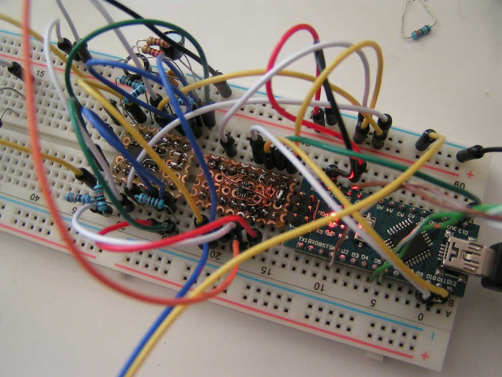
Not so good (wires making loops with big area, components with long legs also making loops):


Better (wires were cut just the right length and routed straight, components terminals not very long):

Well, maybe the capacitors and resistors terminals could have been cut even shorter, like here:  https://www.eevblog.com/forum/projects/t20347/?action=dlattach;attach=1242762;image but you got the idea, avoid big area loops.

- avoid ground loops.  Use star-connection for GND wires, with a single GND point from where all the ground wires are leaving to different places in the circuit.  Do not chain the GND wires one after another.  A single GND point also separates the analog and digital GNDs.

- if the above is not possible in practice, at least keep the analog and digital current loops separated:
https://www.analog.com/media/en/training-seminars/tutorials/MT-031.pdf
https://www.analog.com/media/en/technical-documentation/application-notes/AN-202.pdf

- enclose the low signal stages in a grounded metal shield, shielding makes a big difference, it eliminates the noises induced from the outside of the circuit
22
but we have seen far worse insults being made, and on the internet you have to deal with it unfortunately.

I find it somewhat unfortunate that we are resigned to that. While it may be true "on the internet" at large, there is certainly the ability to curate a community on a smaller scale, if you choose to do so.

And that is most likely why the OP got banned. The moderator chose to keep the community from being abused. Most members here are not out for quarrels, but sometimes you run into them due to others that come here to provoke, troll, or be just plain ignorant.
23
Beginners / Re: Any IPS-like LCD with 7-segment style?
« Last post by Buriedcode on Today at 05:24:57 am »
Mostly because they use TN LCD technology which is indeed old.  IPS is mostly used in active matrix displays - TFT's, with high pixel density, not passive displays with a few segments.

The exception to this ia VA - vertically aligned - displays, which is a similar kind of technology that allows much better viewing angles.  I say exception because, I think only one company makes these and they are used on old character displays that use 0.5mm pixel grids (which is massive compard to modern TFTs/OLEDs).  So it's kind of an odd mix of old and new.

Interstingly, VA dispalys seem to be even better than IPS, but for viewing angle and contrast, its the only technology I've seen applied to non-TFT passive dispalys.  You may be able to find a seven segment VA display somewhere.  The few 16x2 character VA displays I have have stupid viewing angles - at least 170 in both axis'.

I just googled VA clock display and the first result...
https://www.amazon.co.uk/Braun-Fast-Charging-Automatic-Backlight-Adjustment/dp/B09T3GWQV9

surprised you didn't google it first :)
24
Metrology / Re: Experiments with Vref Ovens
« Last post by dietert1 on Today at 05:24:52 am »
Yes, i am using glass thermistors with good results. They are pretty expensive now.
In my oven setups the thermistor serves to control the oven heater, providing very low temperature noise.
There is another thermometer for the critical device inside the oven, usually a pn junction (-2.1 mV/K) or a Pt resistor. An outer control loop fine-tunes the oven set temperature to bring the DUT to the desired temperature. Need to take a closer look at the temperature drift data.
The outer oven i made for our ADR1399 evaluation board also has a glass thermistor and it includes a SHT35 temperature/humidity sensor. After nearly a year the SHT35 temperature may have drifted +10 mK but that isn't a measurement, more like an upper limit. That oven isn't really hermetic and there has been a large drift of humidity. When talking about sensor drift, you want both constant temperature and humidity.

Regards, Dieter
25
What is the 8-knob device that's being manipulated by this fellow's left hand?:


(also can be seen here in case the image link breaks)

It's clearly IBM-branded to some extent, and my best guess is that it's a bank of 8 encoders that could be used for whatever, but used here to control the 6 degrees of freedom in a CAD system. But any specific details on what the device is called or anything else about it would be really interesting!
26
Beginners / Re: identifying Ferrite bead value?
« Last post by Konkedout on Today at 05:18:59 am »
This is a difficult question.  I think ferrite beads are generally unmarked.

What do you mean by "blown"?  Is it physically damaged?  I don't think a ferrite bead will go bad unless it is physically damaged.

They are made of different ferrites so even with fixed dimensions, different types can exhibit different characteristics.

I am not certain why an audio preamp would have a ferrite bead.  One possible explanation is to reduce sensitivity to radio frequency fields.   I had an amateur radio license and a single sideband transmitter when I was young.  Our living room stereo audio equipment would produce loud garbled audio if it was operating while my transmitter was transmitting.  This falls into the broad category of Electro Magnetic Compatibility (EMC).
27
Repair / Re: Please help, how can I adjust this transistor?
« Last post by Harry_22 on Today at 05:15:14 am »
Yes your new video eplains my suggestion somewhat.
Now please measure voltage at two points:
28
Your plot calculated from  of the panel  V, I or incremental internal resistance delat V/delta I?

It seems to be a simple arti=thmit fincetion of P, V, I , R and no relation to the panel life.

We have seen solar panel life depends on


Type of panel construction, quality of mfg eg cheap Chinese or Panasonic, Samsung, etc,

The solarisation degradation is between 3%/yr t 0.5%/yr for most panels depends on the above and the integrated solar intensity over the years.

Consult the panel mfg specs and the  integrated solar intensity  for your location.

https://en.wikipedia.org/wiki/Solar_irradiance

Jon
 

29
Repair / Re: Tektronix DM501A repair
« Last post by Rax on Today at 05:13:22 am »
What I do have at hand from the MG range of products is 404B and 401B (obviously the latter doesn't apply).

I'll give a shot to the 801B product, though the price is on par with the Cadillac of this stuff (Deoxit).
30
Repair / Re: Tektronix DM501A repair
« Last post by Rax on Today at 05:10:19 am »
I glue the needles in place so that they do not leak where they attach to the bottle top.

What do you use for this? I've considered taking this course of action, but been a bit apprehensive about contamination of the contact conditioner from the glue - so I'd be interested in your pick for glue.
Pages: Prev 1 2 [3] 4 5 6 7 8 ... 10 Next