-
TiN.
Good luck buying an 8842A. It looks like 9 were sold in the last 2 days. Strange how that happened.
-
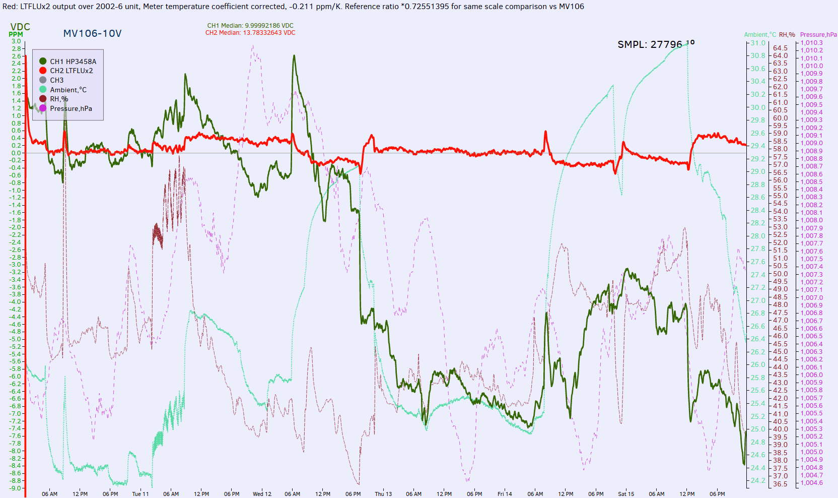
For time being I can only post dual LTFLU-1ACH stability figures (and K2002) over 6 day period (red plot):
TC of 2002 is compensated by math. Temperature swing from 24.4C to 30+C ambient didn't cause LTFLU output to go outside of 1ppm window.
-
I've got 3 731s and re-selected resistors on one of them for near zero TC around room temperature. Fluke got them pretty good, but they can be tweaked a bit better without too much effort- cardboard box and a small light bulb.
-
Today I've received some nice LTFLU-1CH pieces.
I've bought them here for USD 20.- per piece plus shipping, plus Paypal fee plus import taxes etc. (64 Euro):
https://www.alibaba.com/product-detail/new-and-original-electronic-component-ic_60518077974.html
This is a picture from the Alibaba website: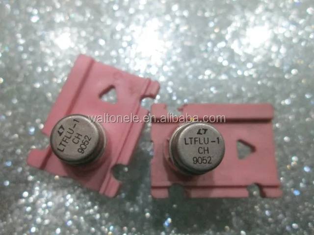
And here are some pictures of the LTFLU-1CH I've received:
(edit: added picture of complete collection 20170817)
-
Getting the LTFLU chips is one part of a reference. These chips are usually use individually adjusted resistors to make them low TC. So one would need either a set of good individually selected resistors or a good temperature stabilization to make it a useful reference.
-
Getting the LTFLU chips is one part of a reference. These chips are usually use individually adjusted resistors to make them low TC. So one would need either a set of good individually selected resistors or a good temperature stabilization to make it a useful reference.
This is very true. I'm working on it and will post my results here. One of my goals is to collect as much data as I can about the LTFLU-1 and post it here, so that there will be probably one day an alternative reference, which can compete with the LTZ1000-CH -
Pretty sure these are fakes, sorry.
-
Pretty sure these are fakes, sorry.
Why?
The last time I've ordered LTFLU-1 on alibaba (different seller, though) a lot of people were convinced, that they are fake (including me). I sent one to branadic and he opened it and took some nice pictures from the chip. It looked very genuine. If somebody is interested, I can send him one piece to open and take some pictures from it from under the microscope.
Here are some links:
https://www.eevblog.com/forum/metrology/the-ltflu-(aka-sza263)-reference-zener-diode-circuit/msg957684/#msg957684
https://www.eevblog.com/forum/metrology/the-ltflu-(aka-sza263)-reference-zener-diode-circuit/msg959228/#msg959228
-
Font is not LTCish enough to me.
 Units apperance from your first link (chips you got before) look way more credible than these.
I can check it for you with my microscope/DSLR setup if you like, as I wanted to build LTFLU version reference module as well (wanted to get 8842A for donoring parts to that purpose, but now after Dave's video chances are small). -
Font is not LTCish enough to me.
Units apperance from your first link (chips you got before) look way more credible than these.
I can check it for you with my microscope/DSLR setup if you like, as I wanted to build LTFLU version reference module as well (wanted to get 8842A for donoring parts to that purpose, but now after Dave's video chances are small).
Why not getting a 8800A? They have the SZA263 in it and are much cheaper than the 8842A.
Thanks for the offer but I hope that somebody from .de is willing to do the photos. If nobody comes around the corner, I'll come back to your offer
-
A first check to see if the chips are real would be to check the electrical performance. If they are acting like zener and transistor, chances are they are real or at least a good copy. There are not that many alternative chips that could give a similar function, though just a zener and transistor as separate parts would fit inside such a case.
Good fakes would be revealed looking at the noise and maybe zener resistance. If it shows low noise and low zener resistance there is essentially no alternative to a buried zener to get that performance - thus very likely a real part, maybe wrong date code. -
@ BU508A
You can directly compare the last batch with the current one on an electrical performance level. However, if you want I can again take some pictures from an uncapped part, but if they are again true parts we have killed another one
-branadic- -
Hello branadic,
You can directly compare the last batch with the current one on an electrical performance level. However, if you want I can again take some pictures from an uncapped part, but if they are again true parts we have killed another one
Thank you for your kind offer. I'll send you one piece of the LTFLU-1CH date code 9052 to you.
Yes, it is a pity to sacrifice them, but I cannot see any other way to verify until we have more electrical data.
I have attached a first draft for a testing circuit for these units. It is based on the 10V reference from a (my) Fluke 3330B.
@ everybody: Any comments to this draft are welcome, especially the critical ones. :-)
Thank you again for your help, branadic. Much appreciated.
Edit: grammar typo
-
Building a reference circuit and checking the performance might be good enough for a check. You may not be able to tell apart and LTFLU and the older SZA version, but one could tell the difference between a high class reference and a fake. There is no easy way to make a fake that is close the performance of the LTFLU. With a chip from somewhat questionable source one would need a throughout performance test anyway - even a new one directly from LT would need some burn in tests.
Even opening the can, will only show you which die it is. It could still be a damaged one or a low quality one (e.g. higher than normal noise). So looking at the chip will not show much about the actual quality - getting original chips (recovered from old instruments) with not so good performance is a real possibility.
The circuit combines the 7 to 10 V scaling with the reference. This kind of looks like the way the reference is supposed to be used. However it might be a good idea to look at the reference voltage only too.
I am not so sure about the two diodes at the reference - they would influence the TC quite a lot and might show aging as well.
The extra divider at the OP also might add quite some errors - it might be better to use something like a divider where the diodes and the 866 ohms are.
I would avoid a jumper directly in series with the zener or critical resistors - this only adds possible drift. I would consider using temperature stabilization, even if only crude: to get a low TC from well adjusted resistors would need some kind of temperature modulation to find the right values - so temperature control is needed in one way or the other. The constant temperature tends to be easier and stabilization could also help with the resistors.
The 4 µF filter capacitor looks rather large - it would determine the crossover where noise of the reference is traded in for the OPs noise - a low filter frequency only make sense with a good OP. I would guess there are more modern OPs than the LM308 with better performance. The gain of the transistor stage is a little lower (like half) in this circuit than in the LTZ1000 circuit - so the OPs performance is more important.
-
Hello,
@ everybody: Any comments to this draft are welcome, especially the critical ones. :-)
I am not familiar with the 3330B cirquit but is it really intended to supply the LM308 from the stabilized 10V.
And is there enough headroom with the zener?
What is J9013? a current source? or is there a pull up resistor missing for the base of the power transistor.
If it is a 10 V source intended as voltage standard I am missing a short cirquit protection.
Further I would place some (EMI-) capacitors directly at the input and the output.
with best regards
Andreas
-
BU508A,
you'd better copy the publicly known 732A circuit. It uses an SZA263, which should be compatible to the LTFLU:
The 732B also first used the SZA, therefore should have a very similar circuit around the RefAmp, like the 732A.
Later 732B models have the LTFLU instead, therefore, I assume that the circuit is dimensioned the same.
At first, get rid of these 1N4148 diodes, they may disturb the constant current to the zener.
Zener cc should be 3mA, so use 1k27.
The collector voltage should be lower, around 7V, as can be derived from the 732A schematic. So use 4k22 over 10k for the divider.
Then, the collector current, i.e. this 39k2 resistor, has to be trimmed to zero T.C. for the RefAmp voltage, i.e. UB or TP 5 in your circuit.
This has to be changed anyhow, due to the lower collector voltage.
The 10V divider should have zero T.C. , maybe by means of oven, and drift free resistors should be used.
I assume, you put the whole assembly inside an oven, at 45 .. 55°C?
Analogue circuit around SZA263 and LTFLU can be found in the manuals for the 5440A and the5720A , page 568.
They each contain two stacked references, so the calculation of the zener currents / resistors is a bit tricky.
Last hint: ZLYMEX published pictures of 732B interior somewhere else, maybe a hand made schematic also.
I don't remember, if this crucial collector-current resistor is visible.. But it would be useful, to know the value, just to have an idea of the ballpark of of the collector current.
In the end, if these are genuine LTFLUs, that easily can be proven by simply building this circuit , and measuring @ room temperature the RefAmp voltage, should be about 6.7V +/- about 10..20%, and determining the T.C. Fakes will quickly be identified by failing on these parameters.
Please don't crack them open!!
Frank -
The circuit with 2 stacked refs will not help very much. It uses a different scheme to provide the collector current (uses the upper reference to supply the lower one and seems to also use parts of the current canceling circuit (and thus a higher voltage but no 10 V of cause) for the upper one.
The 731 and 732 A/B circuits seem to be available: they don't use the diodes but otherwise a similar circuit, but slightly different values (especially smaller capacitors). Large caps might cause extra drift due to leakage and maybe even DA. So especially for the first test I would stay at the smaller values. When changing the caps one might have to check that the circuit will not oscillate - due to the extra gain from the transistor the caps are needed for stability. There is some room for tolerance, but they are not arbitrary. If in doubt a simulation with something like LTspice might be a good idea.
Simple current limiting, like in the later 731 refs might be a good idea, as it reduces the danger of damaging the ref. in case the circuit misbehaves. -
Hello Kleinstein,
thank you for your answer.Building a reference circuit and checking the performance might be good enough for a check. You may not be able to tell apart and LTFLU and the older SZA version, but one could tell the difference between a high class reference and a fake. There is no easy way to make a fake that is close the performance of the LTFLU. With a chip from somewhat questionable source one would need a throughout performance test anyway - even a new one directly from LT would need some burn in tests.
That is my intention with this circuit: not building a reference yet, because there are better implementations around (e.g. Fluke 732A or 732B)
but to determine some of the parameters. And for this the 10V reference module from the 3330B seems to be a good starting point.
And another adavantage is: I have two of these 3330B modules here, so I can do some comparison. There is only one thing: these modules are having the SZA263 assembled instead of a LTFLU-1.
These are my modules:

Here you can find the manual including the schematics:
http://bama.edebris.com/manuals/fluke/3330b/
The schematic can be found in PartA, page 11
Here is a picture from it: Quote
QuoteEven opening the can, will only show you which die it is. It could still be a damaged one or a low quality one (e.g. higher than normal noise). So looking at the chip will not show much about the actual quality - getting original chips (recovered from old instruments) with not so good performance is a real possibility.
I am aware of this and due to the sources I got these pieces from I do not expect high performance units.
But perhaps with cracking open (sorry Dr. Frank) one piece of the LTFLU-1CH we can compare it with the other unit opened which was a LTFLU-1ACH and we will probably spot some differences. This could be also a valuable information.
And yes, I am looking for some damaged units (like 8800A. 8840A etc.) to get some genuine units.
I do not want to dissasemble my 10V ref. modules, they are too valuable for me.QuoteThe circuit combines the 7 to 10 V scaling with the reference. This kind of looks like the way the reference is supposed to be used. However it might be a good idea to look at the reference voltage only too.
Yes, I saw this style in several Fluke designes and it was my impression too, that this reference circuit should be used this way.
That is exactly what TP3 is intended for.QuoteI am not so sure about the two diodes at the reference - they would influence the TC quite a lot and might show aging as well.
I am not sure as well. All I could find was a remark about the forwarding voltage of these diodes (2x 0.7V) and, mabye, some temp. coefficent compensation. I have choosen 1N4148 diodes, because I was not able to find out, what Fluke has used here. I know, that they are not a good choice, so they will just act as reminder and placeholder until I'll have a better idea or more information.QuoteThe extra divider at the OP also might add quite some errors - it might be better to use something like a divider where the diodes and the 866 ohms are.
My impression was, that this divider is part of the sensing. If the voltage is changing then this will be reflected in the neg. input of the OpAmp and since the pos. input is supposed to be stable, the output of the OpAmp will change to the opposite. But I may be wrong here.
QuoteI would avoid a jumper directly in series with the zener or critical resistors - this only adds possible drift. I would consider using temperature stabilization, even if only crude: to get a low TC from well adjusted resistors would need some kind of temperature modulation to find the right values - so temperature control is needed in one way or the other. The constant temperature tends to be easier and stabilization could also help with the resistors.
These jumpers are there for two reasons:
- while open one can do some current measurements
- replace the 50 Ohms trim poti with an external resistor decade for doing some experiments.
Yes, I know, this will add some additional disturbance. But this is just the first attempt and a starting point to learn and improve.
I have also planned to build a temperature controlled enviroment for all measuring. I have also planned to measure the atmospheric pressure as well.QuoteThe 4 µF filter capacitor looks rather large - it would determine the crossover where noise of the reference is traded in for the OPs noise - a low filter frequency only make sense with a good OP. I would guess there are more modern OPs than the LM308 with better performance. The gain of the transistor stage is a little lower (like half) in this circuit than in the LTZ1000 circuit - so the OPs performance is more important.
Yes, that is why I have put this remark "will be replaced" into the schematic. You have suggested earlier in this thread to use a LT1012.
I have on my list the LT1007 and LT1012. I am not sure, which one is the better choice, so I will try both. I have the LT1012 lounging around, so I can start with it. The LT1007 I'll order soon (with some other stuff). If you have other suggestions, I'll be glad to hear them.
Thanks for your input.
Andreas -
Hello Andreas,
thank you for your answer.I am not familiar with the 3330B cirquit but is it really intended to supply the LM308 from the stabilized 10V.
And is there enough headroom with the zener?
Yes, I think so. Fluke did it this way, I just copied it more or less from the original schematic. Please see my answer to Kleinstein.QuoteWhat is J9013? a current source? or is there a pull up resistor missing for the base of the power transistor.
The J9013 is a so called backward diode, also known as back diode, which is a kind of a tunnel diode.
https://en.wikipedia.org/wiki/Backward_diode
But, to be honest: I have no idea what this diode is doing here and why it is used in this direction.
This is one of the mysteries which I wasn't able to solve.
Sometimes you can find a combination of a Schottky diode with a transistor like this:
https://www.quora.com/What-are-the-different-types-of-diodes#!n=12
Scroll down to "7. Schottky diode -"QuoteIf it is a 10 V source intended as voltage standard I am missing a short cirquit protection.
Further I would place some (EMI-) capacitors directly at the input and the output.
No, this circuit is not to be meant as 10V source standard. It is intended to get some data and doing measurements around the LTFLU-1. Later (likely much much later) there will be something like a 10V source standard, based on a LTFLU-1. Well, this is one of my goals. But if can achieve it, I don't know. But I will try (and hoping of a little help from this kind forum. )
)
Anyway, I will create a website around this project and keep you folks informed about the wins and fails (especially the fails )
)
Andreas -
In most of the places one can indirectly measure the current, as the voltage drop at the resistors. In addition this is with very little disturbance of the circuit.
For trimming one could add a resistor in parallel. This also the more usual way to trim stable resistors. So for small adjustments to a 10 K resistor one might add in parallel 100 K in series with a variable 1 K for adjustment. It is the other direction, but would cause less disturbance if unused.
After a closer look, the extra divider seems to be not that critical: it is behind the gain of the transistor and thus only enters with a sensitivity of about 1/100. The other place for the divider would not be much different / better. Other circuits seem to use it as well.
The about 7 V value suggested by Dr. Frank is more sensible, as is leaves more voltage for the resistor and thus increases the gain of the transistor stage.
The 731 / 732 work without the diodes and a different resistor value instead. Even if it might work with the right diodes, using just a resistors (e.g. 1.2x K range) is much easier and less uncertainty in finding the right diodes. The diodes are expected to shift the TC more towards a positive value. This would would correspond to a lower current for the transistor. So one could consider leaving the option to have a diode or two, but usually start with a wire bridge. As the diode is more for adding TC - my best guess would be more like 1 higher current diode (like a glass passivated 1 A diode).
There is not much to gain from opening another chip. The other can still be bad. It is only if the chip turn out to be bad, that one might want to open it. Even if only the zener part is working well, I would not damage it.
For the OP, the LT1007 / OP27 are little on the high side with current noise - so not a good choice. A more suitable one for low noise would be more like an LT1001 or OPA177. The LT1012 is lower bias / current noise than needed. An OP07 should be OK too. With the large caps the OP might want a series resistor for protection in case of a short at the output. The best choice of OP somewhat depends on the transistor current - this could be different without the diodes and also different between samples as the current is used to trim the TC.
I don't think there is a big advantage in using such large caps - the 732 / 731 use something more like 1/10 the size, which is much more practical, especially for a first test, where you want to see the reference noise.
The gain setting divider could be just 2 resistors - with optional later trimming with a parallel part.
From the circuit function the backward diode should be kind of a constant current source - so could be a small JFET. Just a resistor should also work, if the input voltage is reasonable stable. -
Hello Dr. Frank,
thank you for your answer.you'd better copy the publicly known 732A circuit. It uses an SZA263, which should be compatible to the LTFLU:
The 732B also first used the SZA, therefore should have a very similar circuit around the RefAmp, like the 732A.
Later 732B models have the LTFLU instead, therefore, I assume that the circuit is dimensioned the same.
I will do that. Later. But for my first steps here I decided to use the circuit from the 3330B. Reasons:
- I have two 10V modules of this kind (no plans to dissamble them but using as a comparing reference)
- less complex
- probably I can start with some cheap low tempco resistors, e.g. the ones from TT Elecrtronics:
http://www.mouser.de/TT-Electronics/Passive-Components/Resistors/Film-Resistors/Metal-Film-Resistors-Through-Hole/RC55LF-Series/_/N-7gz41?P=1yvjsv8Z1yzv4td
Joe Geller used them in his SVR.QuoteAt first, get rid of these 1N4148 diodes, they may disturb the constant current to the zener.
Zener cc should be 3mA, so use 1k27.
The 1N4148 are placeholders, I will not use them. I have not identified yet, what Fluke has used here, I hope I will and then I will use the proper diodes there.
Btw, the sticker on my modules mention a Zener current of about 31µA, resp. 40µA, so 3mA looks a bit high to me.QuoteThe collector voltage should be lower, around 7V, as can be derived from the 732A schematic. So use 4k22 over 10k for the divider.
I will try that.QuoteThen, the collector current, i.e. this 39k2 resistor, has to be trimmed to zero T.C. for the RefAmp voltage, i.e. UB or TP 5 in your circuit.
This has to be changed anyhow, due to the lower collector voltage.
Yes. the 39.2kOhm, the LTFLU-1, the 100 and the 60 Ohms resistors are all part of one set, which can be ordered at Fluke. They have to match. Same is true for these two wire wound resistors 5.9kOhms and 10.932kOhms, this is a matched pair.QuoteThe 10V divider should have zero T.C. , maybe by means of oven, and drift free resistors should be used.
I assume, you put the whole assembly inside an oven, at 45 .. 55°C?
Yes. I plan to build a temp. controlled oven with some peltier elements. I will place this in an Aluminium case and will isolate this with foam in a bigger case. All kind of electronics which has nothing to do with the LTFLU-1 circuit will stay outside of this Aluminium case (except for the
Pt-100 sensors, of course).QuoteAnalogue circuit around SZA263 and LTFLU can be found in the manuals for the 5440A and the5720A , page 568.
They each contain two stacked references, so the calculation of the zener currents / resistors is a bit tricky.
Yes, I had a look into these manuals. And to be honest: I have some diffieculties to understand how they are working.
Over the weekend I have ordered this book:
http://www.ebay.com/itm/182712686876
I hope it will help me understanding, how those things are working.QuoteLast hint: ZLYMEX published pictures of 732B interior somewhere else, maybe a hand made schematic also.
I don't remember, if this crucial collector-current resistor is visible.. But it would be useful, to know the value, just to have an idea of the ballpark of of the collector current.
Thanks for the hint, I will look for it.QuoteIn the end, if these are genuine LTFLUs, that easily can be proven by simply building this circuit , and measuring @ room temperature the RefAmp voltage, should be about 6.7V +/- about 10..20%, and determining the T.C. Fakes will quickly be identified by failing on these parameters.
I had the same thought, too, but I was a bit unsure about the absolute values. Except for those two mentioned on the sticker.
Interestingly, they are measured at the base of the transistor, not at the cathode of the Zener / emitter of the transistor.
I did it and found a Uz=5.99034V (measured with a calibrated DMM 7510) for one of the modules.QuotePlease don't crack them open!!
Too late, one piece is on it's way to branadic. Perhaps we can find out this way, if there is a difference between a LTFLU-1CH and a LTFLU-1ACH, if there is one. Or do you know by chance what the difference is?
Andreas -
Hello Andreas,
thank you for your answer.I am not familiar with the 3330B cirquit but is it really intended to supply the LM308 from the stabilized 10V.
And is there enough headroom with the zener?
Yes, I think so. Fluke did it this way, I just copied it more or less from the original schematic. Please see my answer to Kleinstein.QuoteWhat is J9013? a current source? or is there a pull up resistor missing for the base of the power transistor.
The J9013 is a so called backward diode, also known as back diode, which is a kind of a tunnel diode.
https://en.wikipedia.org/wiki/Backward_diode
But, to be honest: I have no idea what this diode is doing here and why it is used in this direction.
This is one of the mysteries which I wasn't able to solve.
Sometimes you can find a combination of a Schottky diode with a transistor like this:
https://www.quora.com/What-are-the-different-types-of-diodes#!n=12
Scroll down to "7. Schottky diode -"QuoteIf it is a 10 V source intended as voltage standard I am missing a short cirquit protection.
Further I would place some (EMI-) capacitors directly at the input and the output.
No, this circuit is not to be meant as 10V source standard. It is intended to get some data and doing measurements around the LTFLU-1. Later (likely much much later) there will be something like a 10V source standard, based on a LTFLU-1. Well, this is one of my goals. But if can achieve it, I don't know. But I will try (and hoping of a little help from this kind forum. )
Anyway, I will create a website around this project and keep you folks informed about the wins and fails (especially the fails )
Andreas
The part marked J9013 is a constant current diode which is essentially a JFET with the gate shorted to the source. They use a similar circuit in the 731B where the diode is listed as "Diode, FET, current regulator" with part number E505. Unfortunately, Fluke used the tunnel diode symbol for these current regulating 'diodes'.
In this circuit, it provides 1mA to the base of the pass transistor, Q1. Regulation is achieved by the op-amp shunting this current to ground via the 5.6V zener. The zener moves the required output from the op-amp to 5V for a 10V regulated output so it's not near either rail and allows powering the op-amp from the regulated output.
Orin. -
But for my first steps here I decided to use the circuit from the 3330B. Reasons:
- I have two 10V modules of this kind (no plans to dissamble them but using as a comparing reference)
- less complex
Well this PCB can be used to test your LTFLUs, as this is THE intended circuit for this kind of Reference Amplifier.
That means, it always serves two purposes:
1) Provide constant current for the zener and correct collector current for the serial transistor, for zero T.C.
2) create temperature and timely stable reference voltage, which is always between ground and base of transistor (The LTZ1000 is identical in this sense, but has different topology)
3) Always provide a stable amplified reference voltage to 10V or 15V (inside Fluke 335D). Advantage: only one OpAmp is used for both purposes!
The 10V stability depends mainly on the amplification resistors used. The RefAmp voltage in comparison, is much more stable.The 1N4148 are placeholders, I will not use them. I have not identified yet, what Fluke has used here, I hope I will and then I will use the proper diodes there.
Btw, the sticker on my modules mention a Zener current of about 31µA, resp. 40µA, so 3mA looks a bit high to me.
No, that's not the zener current. If you calculate all voltages in the 3330 circuit, you will see, that the zener current is also 3mA. Would be much too noisy, with 31uA.
Maybe, the LTFLU circuit in the 732B has even higher zener current.
Nope, these 31uA is the collector current for zero T.C.
I have a similar sticker on my 332B/AF reference, 'I =92', that's the collector current, 92uA, which fits to the collector resistor.Yes, I had a look into these manuals. And to be honest: I have some diffieculties to understand how they are working.
Yeah, I also did not yet calculate the whole circuit, it's really tricky.
But if you do, I bet that the zener current will also be a smooth value of 3, 4 or 5mA. That would be the main Erkenntnisgewinn
from these circuits, how to optimally use the LTFLU.
The collector current again will bring T.C. to zero, and has to be tested for each individual RefAmp (on the order of several ten uA) and that's all, what's critical about the RefAmp circuit.
The amplification to 10V or another random voltage, is present also in these circuits, as otherwise they won't work.
This amplified voltage is not used in these calibrators, therefore the calibrator outputs in their 10V range are principally much more stable , than the 732A/B, as the scaling is done by a much more stable PWM.
If you don't need the 10.000V, simply buffer the raw ~6.7 V RefAmp reference, like we've done for the LTZ1000 circuit, and you're done.I had the same thought, too, but I was a bit unsure about the absolute values. Except for those two mentioned on the sticker.
Interestingly, they are measured at the base of the transistor, not at the cathode of the Zener / emitter of the transistor.
I did it and found a Uz=5.99034V (measured with a calibrated DMM 7510) for one of the modules.
Well, you really have to understand the RefAmp circuit. The 'raw' reference voltage is ALWAYS the sum of the zener and the base-emitter voltage. That's identical to the LTZ1000 circuit.
Time stability is achieved mainly by the buried zener. Temperature stability is achieved by this zener / Ube combination, as the zener has a positive, Ube a negative characteristic.
The LTFLU / SZA obviously is better in this aspect, as the LTZ1000, due to a smaller zener voltage, which matches better with the T.C. of a pn structure, which in the end allows for a really precise zero T.C. trimming.
The LTZ1000 sucks in this aspect, as it always has about +50ppm/°C w/o oven, and is not really trimmable to zero T.C., any further.Too late, one piece is on it's way to branadic.
branadic should not open it.. I know him personally, and I think he's a cultivated person..
Frank -
Quote
I know him personally, and I think he's a cultivated person
Thanks for the flowers, but if Andreas wants me to make a picture of the chip I will go ahead. Otherwise I can send him the part back. By the way, I still have the other opened sucker on my desk.
-branadic- -
I have analyzed the RefAmp twin applications 732A versus 732B and 5440A versus 5720A.
ZLYMEXs teardowns and a brief analysis for the 10V references are here: https://www.eevblog.com/forum/metrology/teardown-voltage-standards/msg902855/#msg902855.
There are pictures of a 732B with an LTFLU-1 CH, with 6.6542V reference voltage.
In the principle schematic from the 732B manual, it's obvious, that the topology of the 732B is an exact copy from the 732A.
The collector voltage over the RefAmp is 7.024V, nearly the same as the 732A, 7.032V.
So it's very probable, that the zener diode of the LTFLU is also driven with 3.0mA.
The 732B additionally has three current cancellation circuits.
The reference inside the 5720A is a nearly exact copy of the 5440A, but features also additional current cancellation circuits.
In this stacked circuit, the collector-base voltage (Ucb) of each of the SZA263 / LTFLU RefAmp transistors is kept at zero difference.
By the way, that's the same mode as in the LTZ1000 reference.
This is the only difference to the 732A/B modus of operation of the RefAmps.
Also, both stacked RefAmp were operated independently from each other, regarding potentials and currents.
The amplified voltage of 19.8V is analogous to the 10V in the 732A/B, and commonly used for both stacked LTFLUs to create constant currents for the zeners and the collectors.
The 5440A schematic is easier to understand, as all signal paths are contained on one sheet.
With this knowledge, the complete analysis of the circuit is easily done, see diagram:
The essential insight yields, that the zener diode current is also exactly 3.0mA, and that the T.C. is trimmed by the collector current, on the order of several ten uA.
So I again recommend to test the LTFLUs with the 732A dimensioning.
Frank