...
Just in case Easywave was causing issues there, you could double check by creating the two-tone wave in another way.
I wrote a simple script for GNU Octave to create arb waves in Siglent CSV format. The included example is a two tone sine.
You got the quote attribution mixed up, it was plasmateur who ran into problems with the Easywave-generated waveform. But I second your recommendation to use a different tool to generate the samples. I have not become friends with EasyWave, and have simply used Excel to generate wave samples and export them as CSV.
For the burst and sweep mode you can set each channel up to use the external trigger, now I don't own that model to test that it works, but by using an external AUX trigger you may be able to accomplish what your trying to do
You tee off that aux trigger to the scope and I think that would meet your requirements.
I should point out you can use this to both burst and sweep arbitary waveforms,
It also appears as there is no SCPI command that can be used to capture the screen display which could also be used to snapshot the data.
Anyone had any luck capturing this data via SCPI? Failing that there is always the cell phone camera 
The SDG2000X uses the same screen dump command as all Siglent gear. I have screen dumps via SCPI from SDS, SDG, SDM and SSA devices.
https://gist.github.com/mobilinkd/8a07cc124946c87715c6a1458118411eJust point it at your AWG and give it a shot.
For the burst and sweep mode you can set each channel up to use the external trigger, now I don't own that model to test that it works, but by using an external AUX trigger you may be able to accomplish what your trying to do
You tee off that aux trigger to the scope and I think that would meet your requirements.
I should point out you can use this to both burst and sweep arbitary waveforms,
Problem is that you cannot burst and sweep at the same time. He needs to go from no signal to sweep to zero signal.
Also, when I attempted to generate a two frequency sinusoid with the Easywave, the intermod products, or the sidebands that I observed on a spectrum analyzer appeared to much much higher than when just combining two channels.
Just in case Easywave was causing issues there, you could double check by creating the two-tone wave in another way.
I wrote a simple script for GNU Octave to create arb waves in Siglent CSV format. The included example is a two tone sine.
https://www.eevblog.com/forum/testgear/siglent-sdg1000-arbitrary-csv-file-format/msg1973726/#msg1973726
I'll give your code a shot.
I also tried to generate a CSV with Matlab, and found the sidebands to be higher than just combining two channels.
I'll probably end up running your code and finding out I was bad at generating a CSV. Thanks!
Anyone having problems with the PowerOn Last feature?
Supposed to startup up with last used settings. Sometimes does, usually not and many times comes up with defective waveforms as attached, that can only be fixed by toggling Utility/Mode/Phase Locked and Independent.
Settings that don't seem to be saved are random, frequency, phase lock, waveform ect. The defective waveforms don't seem to correspond with what's in channel 2.
ver 2.01.01.23R8
hw 02-02-00-35-00
Here's a 40Mz sine wave:

Bricking alert!
My unit was running perfectly fine until did the following:
1) Firmware upgrade 22R5 => 23R3, after successful upgrade just continued to use and did following:
2) Used EasyWave to send 8pts wfm, played around with DDS/TrueArb setting etc. Turned unit off while custom wfm was loaded.
Next day unit now shows blank screen after logo. Controls non-responsive. Parameter button is lit. Not recognized as USB device. But LAN shows functional login screen. Do not know user/pass.
 Since did 2 things first time (not used EW before) cannot be sure which activity bricked it. My first idea would be delete custom wfm. Maybe loading it at boot bricks it. But cannot get in....
Ordered online from siglent.eu quite a hassle sending it back etc... Since LAN is working maybe there is some trick to resurrect it? Can firmware be upgraded / downgraded over LAN? Reset procedure? Telnet user / pass?
I realize MrW0lf's message is 2 years old, but I'd like to share my somewhat similar bricking experience and solution.
A couple hours ago I bricked my SDG2042X (modified long ago to SDG2122X by using patched 23R7 firmware and modified XML file). Today I was trying to upload a waveform into the instrument by using low-level SCPI over TCP without needing any NI or Siglent software. I accidentally fumbled my code, resulting in a zero-length waveform stored in the instrument, and then I power-cycled the instrument to clear its stuck TCP state. Bricked! During power-up it displayed the logo for about 25 seconds, then several LED flash briefly, then the LCD goes blank forever.
I unbricked the instrument by connecting via telnet (thanks to the patched firmware), moved into /usr/bin/siglent/usr/usr, deleted my bogus zero-length waveform, power-cycled the instrument, and now it boots fine. Whew!
Maybe that will be helpful to someone else.
@ gammaburst

Thanks for sharing your recovery method.

@ gammaburst
I guess that only works for 23R7 since password required for 23R8 and usual USB boot wouldn't work?
This seems to be the right thread for the

I'm having with my new SDG2082X running FW 2.01.01.23R8
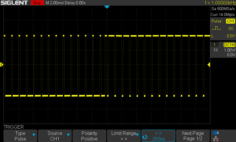
I got it to replace the trusty SDG1050 with its limited output voltage and pulse width, but the "invert" behaves substantially different in the SDG2000 series:
Attached are two "pulse" waveforms when invert is switched with active output.
I'm observing the following behavior:
SDG1050 "invert output" == invert waveform pattern, respecting low and high voltage values as definitive
SDG2082X "invert output" == invert analog output voltage, treating "high voltage" only as an amplitude
is there a way to get the "invert pattern" separately from "invert output"? I'm definitely running into changed paradigms here and not feeling the love for calculating the complementary pulse width each time.
ps. tested 10µs inverted pulses by period:40ms, pulse width 39.99ms, but then the signal is low for a couple of seconds in burst mode (also differing from the previous interpretation.
pps. the logical solution would have been to define LOW 3V and HIGH as 0V, but for no reason whatsoever the firmware enforces HIGH level > LOW level.
ppps. with the new output stage design, the DC bias option is also gone, so I cannot just set it to +5V and have 0V / -5V pulses. Come on, Siglent :/
Someone please explain.
turns out the new way to invert a pattern with
low level == 0V, high level == 3V
is to set
low level == -3V, high level == 0V, output invert == on
... still looks funny with the "-3V" on there while the output is >= 0V at all times. I'm not sure this is the best way to implement pattern inversion.
I have to say that is surprising. When I press "invert output" I expect it to behave as if the low/high values are swapped. That's it. I understand there is a work-around, but outputing voltages outside the limits specified is -- IMO -- wrong.
Interesting, for me "invert" is how SDG20xxX do it: mirror the signal on X axis.
What was not OK for me is that the waveform on the display remained the same, there was no indication on the display about invertion. So, I once fed in the circuit with negative voltage without even knowing it until I measured the output. I spent a lot of time to figure what the problem was, as well phantom "output overloaded" errors. Fortunately, both DUT and the signal gen survived it.
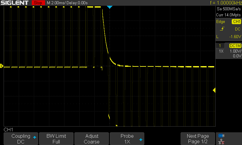
This is how it looks from my SDG1032X......much as I would expect.
Default outputs are of
+ amplitudes.
Following screenshots captured with Single shot trigger.


Outputs set to 0V as low level:
0V low level inverted:

It is extremely simple.
Inverting -1V is +1V.
Function is NOT waveform invert between its top and bottom. Function is OUTPUT invert.
It also works with DC. Set output for +1Vdc and after you select output invert result is -1V.
If user have example pulses: from -5V upwards to -4V and then he invert instrument output he must get - and he get - narrow pulses from +5V downward to +4v.
This is why also this INVERT is in OUTPUT menu.
If user waveform is symmetric related to 0V then it is special case and output invert = waveform invert.
If there is special waveform invert imho its right place is in waveform or wfm parameter menu. Then this kind of invert works so that in prev example original is so that from -5V narrow up pulses to -4V and then result is narrow down pulses from -4V to -5V. And there is not at all this selection.
If there is special waveform invert imho its right place is in waveform or wfm parameter menu. Then this kind of invert works so that in prev example original is so that from -5V narrow up pulses to -4V and then result is narrow down pulses from -4V to -5V. And there is not at all this selection.
Yes - this is the invert feature SDG1050 provides, though it mixes up the two, and this is the feature I would have wanted to use to produce a complementary waveform. They could even call it "complementary waveform" to avoid any confusion with "invert output".
Besides that, there should be an indicator showing the output states (ON/OFF, NORM/INV).
Only need add this to Siglent FW development team wishlist.
Keep OUTPUT invert as it is.
ADD waveform invert function (Invert between its top and bottom value).
Add some clear information to display what tell to user about wfm invert on/off and output invert on/off independent of what selection/setup menu is visible.
Add some clear information to display what tell to user about wfm invert on/off and output invert on/off independent of what selection/setup menu is visible.
I'd say just showing the actual waveform would be enough, if that's possible.
I am trying to automate the modulation of a sinusoidal carrier with a custom waveform. According to the programming manual, this is possible.
This command sets up a modulated DSB-AM carrier with an arbitrary (ARB) modulating wave shape (MDSP)
C1:MDWV DSBAM,MDSP,ARB
However, nowhere in the programming manual does it explain how to set the arbitrary waveform used for modulation.
The obvious command only sets the arbitrary waveform for the carrier, and has no impact on the modulating waveform.
C1:ARWV NAME,custom
And the specific modulating waveform being used is not reported when querying the state of the channel.
C1:MDWV?
C1:MDWV STATE,ON,DSBAM,MDSP,ARB,SRC,INT,FRQ,0.1610824742HZ,CARR,WVTP,SINE,FRQ,28121000HZ,AMP,0.1V,AMPVRMS,0.03535Vrms,AMPDBM,-16.0219dBm,OFST,0V,PHSE,0
Does anyone know how one would, via SCPI, set the waveform used for modulating a carrier on the SDG2000X?
Is there a "complete" list of commands used by Siglent's AWG (including the undocumented ones) floating around? I have found the one for their 'scopes to be a necessity when doing any sort of automation.
rerouter is the specialist in that field. (Siglent's SCPI commands)
You command seems a little corrupted, have not looked into exactly why but it is interpriting DSBAM as AM for unclear reasons
The best reference going for the normal waveform commands is here,
http://www.siglent.com/2014EnglishWebsite/Documents/others/SDG800_RemoteControlManual_RC02008-E02A.pdfAlso my own reference sheet is attached, Its a little hard to parse at times, So I prefer mine to remind you what you need to give for each.
For Reference this is what your command returns as
C1:MDWV
STATE,ON,
AM,
MDSP,ARB,INDEX,0,
SRC,INT,
FRQ,0.1610824742HZ,
DEPTH,100,
CARR,
WVTP,SINE,
FRQ,0.1610824742HZ,
AMP,0.1V,
AMPVRMS,0.03535Vrms,
OFST,0V,
PHSE,0
Ok, so you can set the Carrier via
C1:MDWV CARR, WVTP, ARB
However It is not clear how to select which arb waveform as it does not return an index or a name
C1:MDWV DSBAM, MDSP, ARB, INDEX, 2
This I thought should work, however It also does not appear to let you select the arbwave index,
Edit 1:
OK, you can set the ARBwave, of the carrier, but it looks like you need to use the UI to accomplish it for whatever reason,
Utilitiy Page 4 - AWG - Wave - Arb Type
Edit 2:
For whatever reason the Arb wave of the carrier can be read off, (and probably set before hand) using the ARWV command
You command seems a little corrupted, have not looked into exactly why but it is interpriting DSBAM as AM for unclear reasons
I am not sure what you mean by that. It works on the SDG2122X with firmware V2.01.01.23R3.
The best reference going for the normal waveform commands is here,
http://www.siglent.com/2014EnglishWebsite/Documents/others/SDG800_RemoteControlManual_RC02008-E02A.pdf
Also my own reference sheet is attached, Its a little hard to parse at times, So I prefer mine to remind you what you need to give for each.
Both of these seem horribly out of date. The reference is for the SDG-800 and doesn't cover the capabilities of the X-series AWGs.
For Reference this is what your command returns as
C1:MDWV
STATE,ON,
AM,
MDSP,ARB,INDEX,0,
SRC,INT,
FRQ,0.1610824742HZ,
DEPTH,100,
CARR,
WVTP,SINE,
FRQ,0.1610824742HZ,
AMP,0.1V,
AMPVRMS,0.03535Vrms,
OFST,0V,
PHSE,0
What device and firmware version are you running? The output I reported is formatted the way that the programming manual describes. The reference I am using is
http://www.siglentamerica.com/wp-content/uploads/dlm_uploads/2017/11/SDG_ProgrammingGuide_PG_E03B.pdf. The format of the output I see matches page 23 of that document. There is no ARB INDEX reported. And for custom waveforms, they can only be referred to by name on the 2000X.
Ok, so you can set the Carrier via
C1:MDWV CARR, WVTP, ARB
However It is not clear how to select which arb waveform as it does not return an index or a name
C1:MDWV DSBAM, MDSP, ARB, INDEX, 2
This I thought should work, however It also does not appear to let you select the arbwave index,
Edit 1:
OK, you can set the ARBwave, of the carrier, but it looks like you need to use the UI to accomplish it for whatever reason,
Utilitiy Page 4 - AWG - Wave - Arb Type
Edit 2:
For whatever reason the Arb wave of the carrier can be read off, (and probably set before hand) using the ARWV command
It sounds like you ended up in the same spot that I did. I can hack through it by using the VKEY commands, but that's just
horrible. It is way too slow to meet my needs.
The first thing I tried was:
C1:MDWV DSBAM,MDSP,ARB,NAME,customWhich is what I would hope would work. As you found, there's no clearly documented way to do this. I have a support email in to Siglent USA, but it's likely they are away for a long holiday weekend.
I may try upgrading my firmware to see if Siglent managed to sneak in a few new undocumented SCPI features since R3. I will likely use the hacked firmware so I can scan the installed binaries for SCPI hints.