Recent Posts

Pages: [1] 2 3 4 5 6 ... 10 Next
1
Test Equipment / Re: Choosing between entry-level 12-bit DSOs
« Last post by shapirus on Today at 07:13:43 pm »
and the display persistence hides the deviation of the peaks from the real value.
Persistence will not hide the peaks, it will tend to broaden the trace to include both peaks and the troughs and everything in between over the period of persistence.  Maybe you are thinking of averaging?
We're talking about the same thing, but from different perspective. Yes, the more the amplitude varies, the wider the trace at the peaks becomes. If we want to conveniently see the spread over a period of time, that's where persistence helps. It's like seeing min/max/avg values in the same place.

My screenshots in previous posts show an opposite approach, where a single capture shows how the scope interprets the wave at a single given acquisition.
2
Security / Re: Microsoft repackages apps with a telemetry .NET wrapper
« Last post by tooki on Today at 07:11:27 pm »
So what I mean is that a proper opt-in system makes it clear that the software isn’t, for example, uploading your document to them.

What will prevent to collect the data independently on that opt-in setting?
Not sure what you mean.

Point is, a well written opt-in makes it CLEAR to the user who is reading it what will and will not be collected and uploaded, and what happens to it once uploaded, so that the user can make an informed decision on whether to click “allow” or “decline”.

The same as it happens with MS?
Meaning what? MS has multiple different telemetry systems with separate opt-ins, some for the user, some for the developer to see. This thread is about one where a developer wasn’t paying attention and got their panties in a twist over something they didn’t read when setting up their installer.
3
Beginners / Re: uCurrent Gold Schematic
« Last post by uf29857 on Today at 07:07:35 pm »
Thanks for poinitng it out. I forgot to connect output feedback.
I have placed NMOS in antiparallel with the lowest shunt resistor for protection.
Q1 will check again and will remove it as suggested in the previous comment.
4
Repair / Re: Looking for a small PCB-mount microswitch with a long stem
« Last post by tooki on Today at 07:04:15 pm »
You’re not finding them because these are not called microswitches. Panasonic calls them “detector switches”, Omron “detection switches”. Look at https://www.digikey.com/short/hv315jf2
5
Power/Renewable Energy/EV's / Re: Totem Pole PFC is over-hyped?
« Last post by temperance on Today at 06:59:16 pm »
Quote
but, what stands out for me in this thread, as famous last words, is "software is not a issue." Hand wave a issue because a big number popped up and then follow that up with some figuring about the competition (and assuming their sane). A level V systems engineer wrote this?

What exactly are you trying to say? Micro controller driven power supplies are a reality. Check manufacturer offerings from TI, Analog devices, Infineon,...

My point is was and will always be that improving efficiency is very difficult and every method has it's own set of problems, shortcomings and limitations. The statement made by the OP doesn't stand without a real working proto type.

Quote
3) attempt common sense based trouble shooting

Thanks for the excellent advice. I usually replace random stuff until things work.
6
Other Equipment & Products / Re: Any opinions on the Aixun T420D?
« Last post by Tor Björn on Today at 06:58:11 pm »
Do you have a photo or diagram of how the wire to the tall stand is connected to the main station?
Yes, you can see additionally installed pin #4 in plug of T115A handle on my photos in post #115. One end of extra wire is soldered to this pin, other end - connected to the "tall stand" (pre-disabled from "stanby" yellow pair internally in holder).
Is that standby pin just a ground pin or something different?
"Stanby" pin #4 and "extractor" pin #3 are internally pulled up (to 3.3V) different pins of microcontroller. When you insert a handle to cradle (connected to pin #4) or tip of cartridge to extractor (connected to pin #3) you push these pins to gnd, and can see a state "stanby" or "extract" on station's display. T245 handle have a gnd on metal ring, T115A have a gnd both on metal tip and on metal shank near rubber cable gland.
Wondering if might not be possible to internally connect the standby pins of both channels inside the main station so there's no need to run an extra wire.
No. "Stanby" pin #4, "extractor" pin #3 of channel #1, and "Stanby" pin #4 and "extractor" pin #3 of channel #2 are FOUR different pins of MC.

In hindsight, the cheapest maneuver was probably buying a T405 unit and hoping to get sent one with T420D firmware...
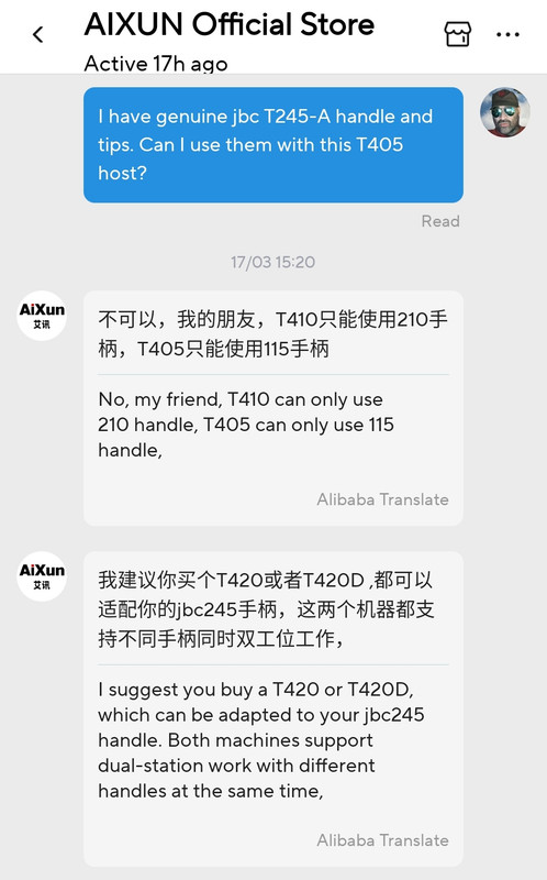
All sellers warned me that T405 only works with T115 handle and T410 only works with T210 handle:

Maybe this words are "chinese half-truth" and these kits  have the same hosts with same transfos (less powerful than T420/420d) that can work with both T115 and T210 handles but not at same time.
7
Projects, Designs, and Technical Stuff / Re: Corrosion on DIP pins
« Last post by tooki on Today at 06:57:16 pm »
wont split open but rust will get to bondwires if it continues
even solder is tarnished  :-+
I wouldn't be surprised if the caps had leaked, and the electrolyte is the reason for the rust.
capacitors are not as corroded
Not surprising, since the capacitor’s leads have to be made of a material compatible with its own electrolyte!
8
Having mostly mastered CAN Open (well fix one problem and now your see the next problem more clearly  :-DD) I have been looking at how to refine my motor control.

I have two motors that are couple to the load with some elasticity - literally. Lets just approximate the system as two motors that drive a common shaft via belts and the are mounted such that for the shaft to rotate the motors rotate in opposite directions.

So I immediately discarded the idea of using the motors in speed controlled mode. A short experiment proved my theory right, One motor will take over all of the load delivery while the other will be left lazy. I want them to share.

So I went with Torque control. I send a sync message to the network, get the speed of the motors back, average that speed and decide on how to change the torque, then I send the new torque setting. It works OK, I am still debating with myself as to whether I should update often with small values or less often with larger values. At his point I started looking around for information on how to consider setting up a DS402 motor driver to run in torque mode with my external controller (CAN Open master) doing the speed control.

I came across an example of a non CAN Open motor system for a conveyor belt where one motor is run in speed control mode with additional "helper" motors running in torque mode. EUREKA!

But that makes my wonderings about precise settings even more relevant as now the two motors will have different behaviors while achieving the same thing together. The idea is that I no longer need to send a sync message to get the speed from each motor, process that and issue new torque commands. Instead I would send the speed required to one motor and send the sync message. The speed controlled motor will respond with it's target torque as well as actual torque. The torque controlled motor will be set up to receive this target torque as it's torque demand and so setting both motors to the same torque. In this way there is no race between the two motors with one taking over but I get to use the much faster and certainly better designed speed control loop in the motor driver than my own machination that is just keeping up.

Obviously that the motors are mounted opposite ways round is a problem as whatever the torque of one motor is the other needs the negative of the number. I currently do this in my program before sending the numbers out to the two motors. There is a setting somewhere for the encoder that basically reverses it's interpretation, need to look more into this one to see if there is a way to overall reverse the motor direction.

What I do wonder about though is the tuning of the two motors works. I guess that as the helper motor is just that it's torque does not need to be identical but I also do not want to confuse the speed control loop in the speed controlled motor. I suspect that the torque controlled motor needs to react faster than the speed controlled one so that it adds or subtracts it's torque in time for when the speed controlled motor is expected to achieve it's speed and so not confuse the system.

Has anyone ever done this?
9
Beginners / Re: Convert US standard 115V to International 230V
« Last post by tooki on Today at 06:53:57 pm »
As a practical matter, most modern electronic equipment is designed to work equally well at 50 or 60 Hz.
The more likely problem is 100 vs 120 vs. 240 V.
It’s already established that the device runs on two universal-input SMPSs. Model numbers much earlier in the thread.
10
Beginners / Re: Convert US standard 115V to International 230V
« Last post by tooki on Today at 06:53:02 pm »

The transformer really doesn't care if it's 50 or 60 Hz, it'll run fine either way. If it's a
50Hz transformer it'll actually run slightly cooler at 60Hz because it may have more
copper in it. And a SMPS will generally also run OK at either line frequency.
Unless there's some kind of frequency sampler circuit that wants to see a particular
line frequency(which would be rather odd), it's not worth the bother to design the
device for one or the other.
There is no transformer, just two SMPS.
Pages: [1] 2 3 4 5 6 ... 10 Next