Recent Posts

Pages: [1] 2 3 4 5 6 ... 10 Next
1
The ckt board holder is stable and holds.  Much better than the alligator clamping thingies.  The Proskit is a joy. We had to heat and strike to desolder.  The Iwiss tool does a great job and is highly polished.

2149177-0

2
Buy/Sell/Wanted / Re: The Bad Shopping Experience Thread
« Last post by AVGresponding on Today at 12:47:25 pm »
Scam warning.  I was scammed in the sell/buyer thread by this person purchasing a Leader 3217.  It was finally resolved by paypal on my end.   I hope Admins will back list him, not sure where to post this?


M3Knight - EEVblog user name
harveygrout75@gmail.com - Another Email account
markevans56@yahoo.com - Mark Evans is the paypal recipient

You need to email a mod/admin. They do not necessarily see posts unless they happen to read one at random or go to see something that has been reported to them.
3
General Technical Chat / Re: Cable Management
« Last post by EPAIII on Today at 12:47:23 pm »
I have been in electronics for over 55 years and the meter and test cables have always been a problem wherever I have worked as well as in my own shops. Just a few months ago I came up with a new idea and, so far, I really like it.

Being 80 years old I have a number of prescriptions. Being cheap, I have saved the empty, plastic bottles the pharmacy packages them in. All the pharmacies I have used have used a yellow plastic bottle with some kind of child safe cap. A pair of close wire cutters, the type made with sheet metal, makes short work of removing the lock on the bottles that I have collected. I have many, many of my small parts stored in these Rx bottles. For the most part I use the bottles with just the child lock cut off but when I decided to store my meter cables in a couple of them I decided to use my power band saw for metal work to cut the tops completely off, at an angle. I did this due to the shortage of space on my electronic work benches. I plan to make a base for the ones in the first photo with my 3D printer as soon as I can get a round-tuit.

As seen in the second photo this is also a good way to store computer cables as well.

In addition to that, I have literally hundreds of small parts stored in these Rx bottles. I print round labels for the tops and consolidate them in cardboard bins and mini-bins on shelves in my shop.

And the best thing about using these Rx bottles is they are free. Well, I don't pay anything extra for them, that is.


4
I have no direct experience of using it for mains quality so take it with a pinch of salt, but I find distortion very hard to judge on an oscilloscope. Other problems such as transients are by definition occasional so won't show up unless you have the trigger just so.

A general purpose piece of lab equipment that would be more suitable is a spectrum analyser. That seems like overkill but it only needs a low frequency response - maybe to the 5th harmonic of 60Hz  to show distortion.

But a spectrum analyser offers far too much to be used only for this and so is not normally used. There's a reason sapecific test equipment such as mains power  analysers exist : it's customised to do the exact job and robust enough for field use. There are also scopes that are ruggedised for the job - such as the obsolete Tek 555PS - and have appropriately rated probes and inputs that are suitable for use on high power circuits (it's easy enough to measure voltage with respect to earth, not so easy with respect to neutral).

My recommendation would be to look for a specialised unit but buy it secondhand.
5
Is IWISS getting better? Look at the polish.

2149147-0
6
Test Equipment / Re: Siglent SSA 3021X... Ooops
« Last post by Joel_l on Today at 12:42:49 pm »
This is helpful, thank you! Guess I'm not the only one.

Thanks
Joel
7
Beginners / Re: LM324 Power Supply with variable voltage and current
« Last post by xavier60 on Today at 12:37:39 pm »
Initial thoughts are, the fans only can be powered from the 2x15Vac transformer.
The tap changer might be able to be powered from the 2x12Vac transformer with modifications so that it can accept negative sensing input voltage.  Because the DVM can only measure positive voltage, it needs to be powered WRT the PSU's negative output. So the unmodified tap changer might as well be powered from the same supply.
 Keep in mind that ground on a Harrison PSU is the positive output.

Can you please be more explicit ? Are you trying to explain that the tap changer could be powered if I modify the schematic ? Regarding the DVM, I didn't understood.
The tap changer could be powered from the same supply as the LM723 if the tap changer is modified to input negative sensing voltage.
But there is no point because the DVM can only accept positive sensing input voltage so needs to be powered WRT the PSU's negative output terminal and the unmodified tap changer can also be powered from the same supply as the DVM.
8
Oscilloscopes are for displaying signal waveforms, not creating them.

Basically yes, but the Hantek mentioned has a built-in signal generator (AWG).
This can be used to generate pulses, but not patterns (except perhaps within limits with an arbitrary waveform).

I don't quite understand the question and am therefore not sure whether he needs an oscilloscope at all.

The solution with the Arduino seems plausible.
9
Projects, Designs, and Technical Stuff / Re: Opamps - Die pictures
« Last post by Noopy on Today at 12:36:56 pm »
They describe it as "chopper stabilized" in the datasheet. If you think about it, the part S1, gm1, gm2, S2 is a chopper amplifier: S1 chops the differential input voltage into a square wave, the linear transistors amplify the square wave, and S2 demodulates it back into DC by sampling the peaks. To avoid differential subtraction of peaks and valleys at this point, gm3 works as a DC servo of sorts and ensures that the valleys are fixed near some internal "ground" potential.

The output of the chopper feeds gm4 and gm5, which provide additional gain. And the whole chopper is bypassed at frequencies near the chopping frequency and above in order to reduce aliasing artifacts and achieve GBW much higher than the chopping frequency.

Of course the "auto zero" explanation about gm3 canceling gm1 offset voltage and a bunch of sample-and-hold circuits making it all work is valid too. I'm not sure what the difference between "chopper stabilized" and "auto zero" is supposed to be, and if there is any real difference at all. Maybe it's only marketing talk.

I have read some articles and it seems that (today) it is common sense that "Auto Zero" is used for sampling circuits which meassure the offset and subtract it from the amplified signal. "Chopper" is used for for circuits that modulate and demodulate the signal and so loose the offset on the way. But the naming is mixed up a lot...  :-\
You are right, the sampling circuit is somehow a modulation too but in my view it´s a lot more a sampling thing.

"Stabilized" (chopper or auto-zero) means that there is a high frequency path parallel (at least that is what the articles said I have read).


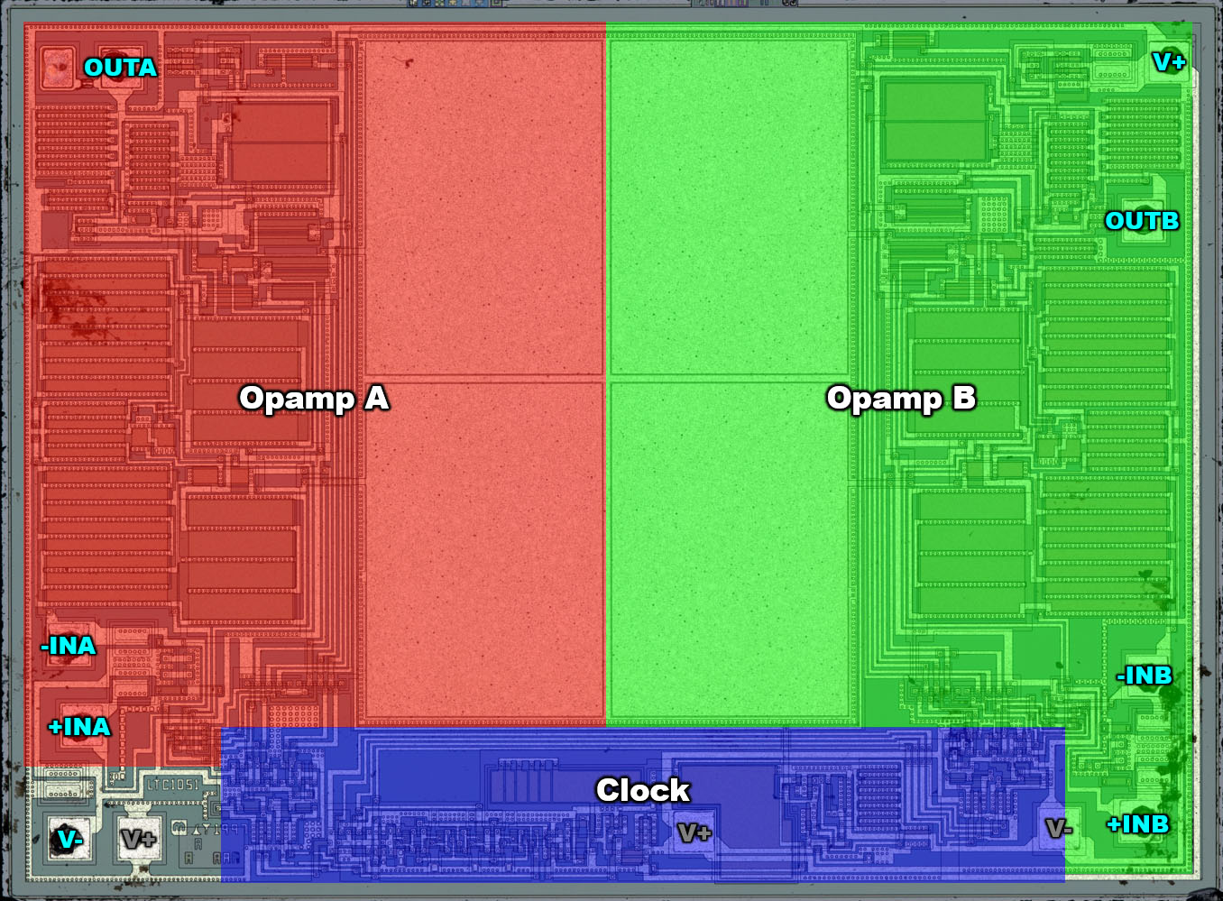
There are three unused bondpads in the lower area. These are additional options for connecting the supply potentials.
It's probably same thing as with MCP6024: two dual dice can be installed together to realize a quad. The top die gets its V+ in bottom left and V- in bottom right. The bottom die is rotated 180° so its supply connections are swapped.

I suppose it works out cheaper than designing a quad die and disabling half of it for the dual ;)

A good explanation!  ;D


The circuit corresponds to the block diagram in the LTC1052 datasheet. The datasheet states that the amplification factors of the amplifiers gm1 and gm6 must be as equal as possible for proper function. Furthermore, these are the amplifier stages with the high amplification factors. Accordingly, these two sections are relatively large and have the same structure.
These things look like ordinary PMOS differential pairs with PMOS current sources in the middle between gm1 and gm6 and NMOS current mirrors.

Hmm, how far are you from a complete transistor level schematic of this opamp?

The circuit is not very complex and the complete schematic would be near but I somehow don´t like MOSFETs...  ;D
10
Beginners / Re: Where to get datasheets of this part
« Last post by Terry Bites on Today at 12:34:22 pm »
Try a vendor of the ic.
eg www.sierraic.com
Search for the ic and use the query box to get a datasheet.
Pages: [1] 2 3 4 5 6 ... 10 Next