Recent Posts

Pages: [1] 2 3 4 5 6 ... 10 Next
1
In case I didn’t specify, or specify correctly, all my measurements were to chassis ground.

Next time I’ll try a different ground; and shorter.
2
I realised I was cheating a bit in my previous measurement. I was running in "two cable mode" i.e. voltage on "normal" cable and measurement on the Triax. So no wonder there was very little leakagecurrent.

When running in "single cable mode" feeding voltage though the triax, i got around 0.1 pA at 1000 volt.

I tested my original ADCMT cable for my ADCMT 8252 electrometer with an adapted. That comes down to noise floor of the 5450 in single cable mode. So I have some more tweaking to do. 
3
Metrology / Re: Why don't we see more TDC based high-resolution ADCs?
« Last post by nimish on Today at 04:46:37 pm »
You will have a design limited by the noise performance of the high bandwidth comparator, and you will be disappointed. If you look at the ultrasonic flow applications for which the GP22 was designed, you will find they are characterised by needing to measure, to a few 10's of picoseconds, the time between 2 very distinct events. Its only that the 2 events are very distinct that the design works well. A somewhat fuzzy comparison, limited by noise, at very high speed, isn't going to do well.

Seems to work for CERN: https://indico.cern.ch/event/243655/attachments/415393/577145/elx-trigger-daq-p1.pdf (slide 30)
How does slide 30 disagree with what I said? Their "hit" is a "very distinct event". Not a noise soaked output of a high bandwidth comparator.

I would like to see your dual/multi-slope adc that doesn't involve a precision comparator/trigger somewhere
Huh? I think you've lost the plot.

Exactly how do you think an integrating ADC works?

https://www.analog.com/media/en/training-seminars/tutorials/MT-027.pdf
4
Projects, Designs, and Technical Stuff / Re: Homebrew Lock-In Amplifier
« Last post by Picuino on Today at 04:44:51 pm »
I can't find the “Shorty” software to study its operation.
The original link is broken:
+ https://hackaday.io/project/3635-shorty-short-circuit-finder
+ https://github.com/jaromir-sukuba/shorty/blob/master/fw/shorty.ino  (Link to firmware)

Where can I get it?
Can someone upload it?
5
Beginners / Re: 5V buck converter debugging
« Last post by davegravy on Today at 04:44:06 pm »
I notice two things. One, Cboot/SW4 indicate a 50% duty cycle gate drive, however, we do not see the 0 to 3.7V pulse at 50% duty cycle that is expected at SW1/2/3.

The other is that indeed the input voltage rail is collapsing which likely leads to the IC turning on and off because of it's 3-4V under voltage lockout. What is your input current limit?

100mA. I think I saw 1A on the first one that I fried. If I need to go higher than 100mA, any suggestion of what's a safe limit? (I won't hold anyone responsible if I blow another  :)).

Can you confirm that the picture of SW1/2/3 is accurate? It looks identical to the "Vout (Vin=3.7V RMS)" picture.

I reproduced the same waveform this morning, but read on for more context.

I recommend using one shot/single mode to remove the other waveforms from the screen. Easier to read that way.

I'm struggling getting 'single' to work on this scope. I see a blip of the trace when I hit the "reset" button on the trigger, but then the scope goes blank, ie the trace isn't persisted. The reference-manua isn't very beginner-friendly. I'm sticking with 'auto' for now.

I noticed my probe has a filter built in and looking up the model # (PM8918) it seems it's limited to 4kHz bandwidth. So I broke out a bnc cable to my own leads (6" length) confirmed I measured a clean 1MHz square wave from my function generator with it, then remeasured.

At the 0.1us/div setting it's all HF noise now. But something interesting is going on at ~1kHz fundamental:

Vin


SW1/2/3


Vout


SW4


Cboot


Vin at 0.1us timescale is just noise, the other nodes look fairly similar:


Safe to assume the noise is contained within that 1kHz "blip" that's occurring?
6
Microcontrollers / Re: Memory model for Microcontrollers
« Last post by jnk0le on Today at 04:43:32 pm »
but as far as anyone knows they are not getting money for this.

There is a lot of money involved in this kind of trolling if you consider potential use for psyops.
Either by delivering it directly or just to farm a credible accounts to be used later by "professionals" (instead of e.g. a blatant "green accounts" that suddenly have a lot to say about the rus-ua war).

And psyops term is not exclusive to the military grade ones, but even a trivial purposes like whistle marketing, or purely political.

If there is demand, there are companies selling appropriate services.
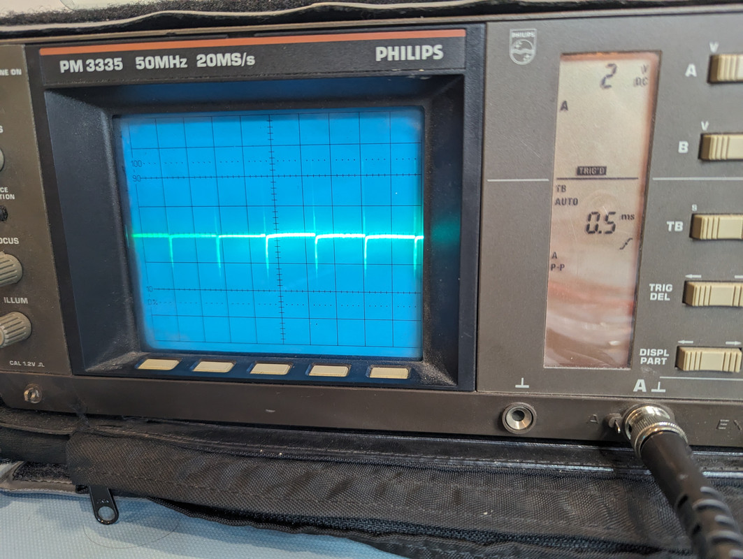
And if we are talking about commercial use, look at his 3rd photo:


neosoft - looks like company name, there are multiple similarly named companies but this one (already mentioned) explicitly mentions "AI" in whole portfolio:
https://in.linkedin.com/company/neosoft
https://www.neosofttech.com/services/artificial-intelligence-machine-learning/

neosoft-ThinkPad-X270 - default ubuntu hostname formatting: https://superuser.com/questions/734998/where-does-ubuntu-get-the-default-hostname

-W10DG - most likely inventarization number, typical in corporations

- offending company is also located in India
- reverse image search yields this thread only (unlike the "traffic light" or ebay/aliexpress one: https://irq5.io/2017/07/25/making-usbasp-chinese-clones-usable/ used here https://www.avrfreaks.net/s/topic/a5CV40000000ajRMAQ/t394567)
- what is even the purpose of photografing this, are we yet to see another GPT-question related to berkeley output from `size` program?
- he seems to be using win11 normally https://www.edaboard.com/threads/uart-communication-for-sending-integer-values.408205/ , https://www.avrfreaks.net/s/topic/a5CV40000000ajRMAQ/t394567

Also, the kittu* accounts started activity few months after the Yannic video about GPT-4chan.

If true, we are probably seeing that someone is testing something here. (like reactions, time to compromise or this is a decoy and there is higher quality bot posting from stolen accounts etc.)
7
Other Equipment & Products / Re: QUICK 861PRO 1300W - Voice commands
« Last post by jwehle on Today at 04:42:38 pm »
My question regarding using the cooling feature was in terms of safely cooling the piece being reworked.
8
Microcontrollers / Re: Starting with STM32 (NUCLEO-L412KB)
« Last post by coromonadalix on Today at 04:42:08 pm »
for the STM32_Programmer_CLI.exe error

You have to install them to their default locations,  and for Arduino IDE,  i use the full install,  not the portable one 

took me hours to figure this out,   no help from ST nor Arduino   |O |O

Once you select the right board type, programming interface, com port ...  and once you install the libraries related to some projects,  mostly the FreeRTOS  ...  Timer ...
9
Some thoughts I've had:...
if its for small batch, you can do whatever fancy technique like that. for more mass production alike, i would make pcb adapter on top of mother/main board.. like this...


reflow and hand solder friendly, you can stack them easily 2,3 or more for more height... fiddling with smd resistor stack is not fun. if LED requires heat transfer, you can design pad underneath the LED and then vias right down reflowed to main board. ymmv.
10
Metrology / Re: DIY 0.1 to 10Hz Noise Amplifier
« Last post by trtr6842 on Today at 04:39:08 pm »
Interesting script!

Here is what I've got: The script is trying to add 100 sines together, approximately log-spaced from 0.02Hz to 10Hz.  Since a lot of the lower ones overlap when rounded to the nearest multiple of the base frequency, the script ends up giving 70 tones.  To get a small enough resolution bandwidth on the FFT, the pattern is repeated 4 times before the FFT is computed.  Right now each sine has the same amplitude, but I do want to start shaping the amplitude profile to optimize SNR for the expected LNA frequency response.

Basic sum-of-sines, no phase shift:  Vpp = 28.6x the amplitude of a single sine


Flipped phase for every-other frequency:  Vpp = 23.7x the base amplitude


Linear phase shift, each frequency's starting phase is evenly spread out over 360°, Vpp = 16.9x the base amplitude, which feels pretty good considering there are 70 tones added together.  I'm curious what kind of Vpp to tone amplitude ratios the random iterative script can accomplish.


Here is the script I used to generate the time domain signals:
Code: [Select]
import numpy as np
class WaveformMath:       
    def sum_logspace_sines(n_points, f_max_ratio, n_f, n_cycles=1):
        # n_points is how many time-domain samples you want.  The resulting signal will have fewer tones, since tones that are too close together will be skipped
        # f_max ratio is the ratio of the max frequency to the min frequency (the lowest frequency is normalized to 1.0, so this is how you define the max frequency)
        # n_f is the number of frequencies you'd like
        # n_cycles is how may times you'd like the pattern to repeat within the number of points given

        x = np.linspace(0, n_cycles, n_points)  # 0.0 to 1.0 normalized sample time
        y = np.zeros(n_points)
        f_log = np.logspace(0, np.log10(f_max_ratio), n_f)  # ideal set of log-spaced tones
       
        f_approx = []
        f_max = 0
       
        for f in f_log:
            fa = (f*n_cycles//1)/n_cycles  # round down to nearest frequency
            if fa > f_max:
                f_approx.append(fa)
                f_max = fa
               
        for i in range(len(f_approx)):
            # y += np.sin(2*np.pi*f_approx[i]*x)  # straight sum
            y += np.sin(2*np.pi*f_approx[i]*(x+n_cycles*i/len(f_approx)))  # linear shifted phase based on index
           
            # if i%2 == 0:  # Flipped sign every other frequency
            #     y += np.sin(2*np.pi*f_approx[i]*x)
            # else:
            #     y += np.sin(2*np.pi*f_approx[i]*x*-1)

        # print('Number of tones: %d' % len(f_approx))
        # print('peak: %.3f' % (max(y)/2-min(y)/2))
        y = 2 * y / (max(y)-min(y))   # normalize Vpp to 1.0
        # print(y[0])  # print initial DC offset (DC average is stil 0)
           
        return x, y
Pages: [1] 2 3 4 5 6 ... 10 Next