The latest acquisition of the T&M variety was an HP350D attenuator. USPS claims it was delivered last Thursday. I'm sure the are right, but I'm also sure that where they delivered it was not at my address.
Aaaaand, of course, USPS doesn't even allow one to open a tracking request until 7 days after the promised delivery data, notwithstanding that a package claimed as delivered might be far more easily found if sought after immediately. I'm going to try to reach the local postmaster today by actual telephone to see if he can at least look up the GPS location where the package actually was located when it was scanned at delivery.
All the delivery services truly do suck at one time or another, but there's something to be said for the UPS habit of photographing the item at the delivery location. USPS could learn a thing or two from that.
Rick "usually USPS doesn't report delivery when it wasn't delivered--they just lose it and go silent" Denney
The HP350D did finally appear--right where my wife had put it the day it arrived. Sigh.
It works fine, or at least it did after I cleaned the rotary switches.
And I finished putting the Thaikits CH-012 curve tracer together. Pics:
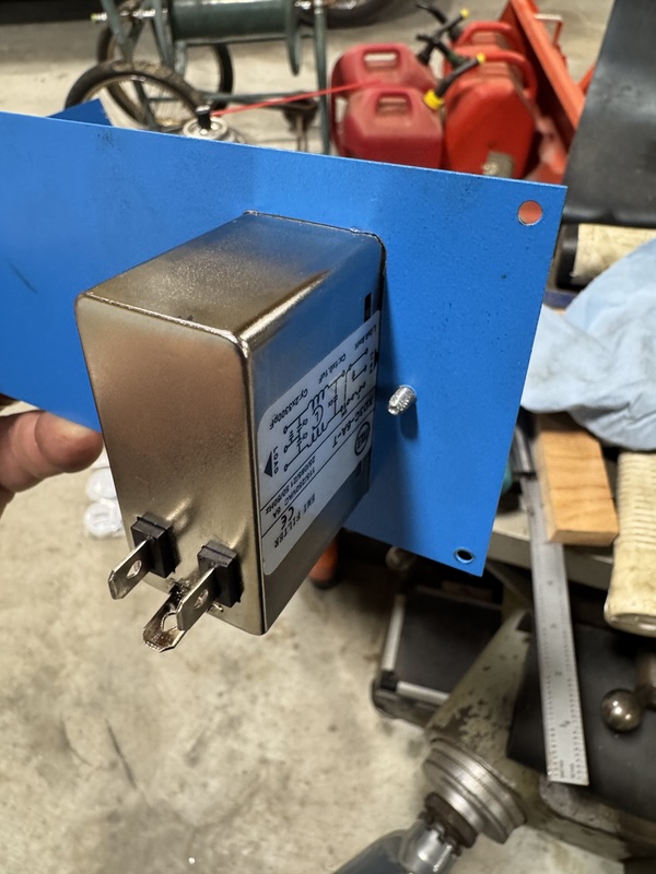
I started with the power cord connector. I used the milling machine to cut the rectangle for that device. The one I bought has an integral EMI filter comprising a common-mode filter followed by a differential filter, which I think added about a dollar to the price I paid for it. It also had a fuse holder and a proper power switch, so it was a useful package. I used to hate things like this (and meter openings) until I added a Bridgeport mill to the shop.
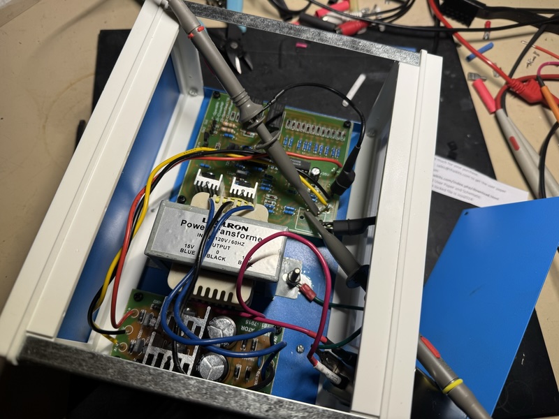
The kit came with a little linear +/- 15VDC power supply--I had to buy a transformer for it. I located the transformer centrally so that wouldn't be too heavy on one end. I thought the cheapie Amazon box I bought was abundantly large, but I never seem to buy boxes that are too large even when I intend to. Here is is after the PCB's are mounted and the power supply hooked up, but before making the front panel.
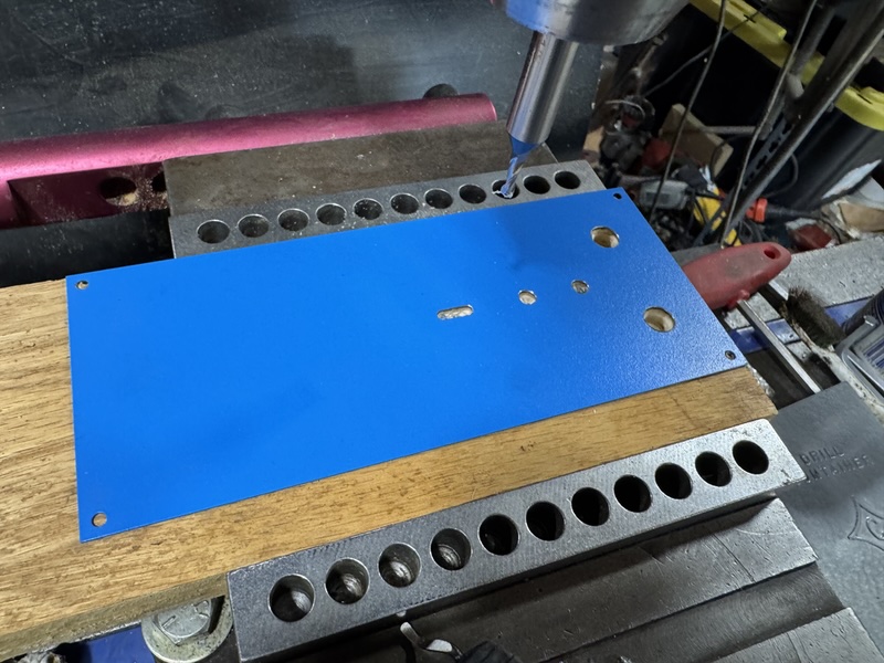
Again, I used the mill to precisely locate the holes on the front panel. (The plate was screwed down to the piece of wood used as a backing fixture when I cut the openings.)
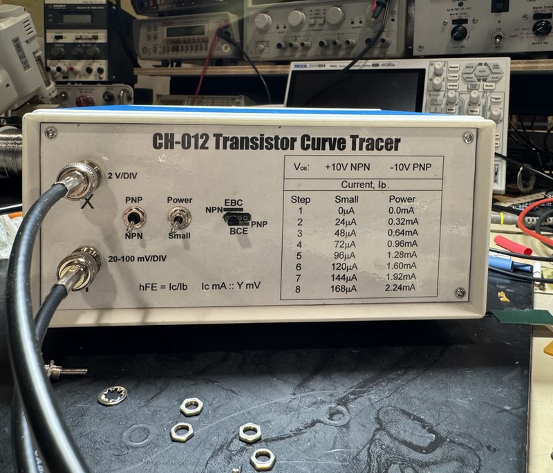
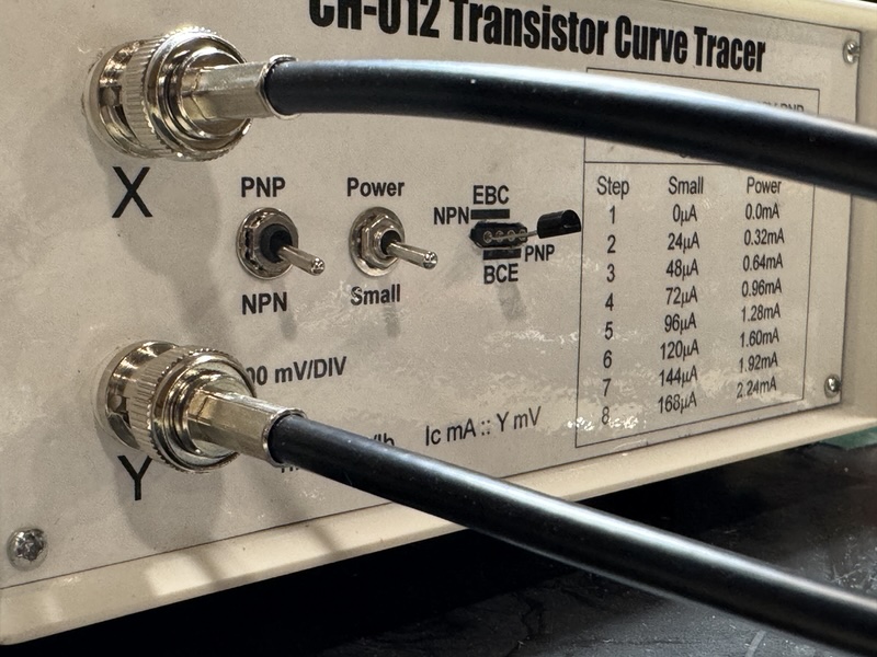
I used coaxial cable to wire up the X and Y connectors, and insulated connector bodies to isolate the chassis ground of the PCB from the case. I made the front panel by drawing it up in Corel Draw, printing, and then laminating it in heavy plastic. I glued that to the metal panel using 3M Type 77 Spray Adhesive. I had space on the front panel which I used to summarize the info on the sparse downloaded material that accompanies the kit, so I wouldn't have to look that up. The small switch on the right was part of a half dozen of them that I bought from Digikey, but these were the worst junk switches I've ever seen. Just terrible. The switch would melt if the soldering iron spent more than about three seconds on the tab, the tabs weren't tinned effectively and I had to flux the crap out of them to get the solder to stick, and if you tighten the clamp nut more than about finger tight it will pull the threaded barrel right out of the switch body. I was able to use one of the six I bought--the other five ended up in the trash in various states of destruction. The other switch was cheapie I bought at Radio Shack probably 20 years ago that I had lying around--I wish I had two. I used a 4-position header socket, similar to what the kit-maker used on the PCB, which is great for inserting a small transistor like the 2N4401 shown here. I'll make a set of pigtails with clips for larger transistors.
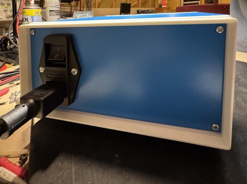
Here's the back with the power plug:
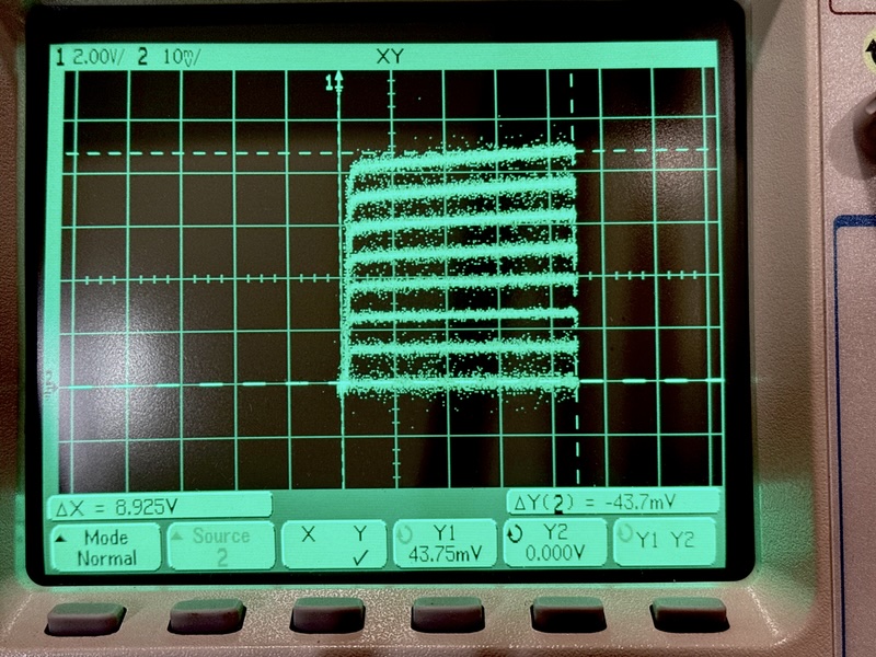
I get that these are not much more use than showing pretty pictures on scopes. But I'm curious as to what you guys would interpret about this transistor knowing the currents that were pulled through it (shown on the front panel) and the traces on the scope. I've put cursors at the four corners to show the voltages. Lower left is zero volts on both X and Y. Upper right is 8.9V on X and 44 mV on Y. I'm thinking this means the hFE gain is about 260, which pretty closely matches the data sheet. (I would have used my Tektronix analog scope for this, but the XY setting on the selector switch seems to be in need of cleaning.)
Rick "comments welcome" Denney

 Home
Home Help
Help Search
 Login
Login Register


