Does a particular terminal software work better than another? Between Putty, Ultra Sigma, and Realterm, I am 0 for 3 in telnetting to my SDG2042X.
Has anyone else seen this? As I turn the dial to change the amplitude (0.1dBm steps into a 50ohm load I'm probing) the output has discontinuities.

Has anyone else seen this? As I turn the dial to change the amplitude (0.1dBm steps into a 50ohm load I'm probing) the output glitches.
Hi
The attenuator is running on (slow) relays. The output is running on (fast) logic. There will always be a delay when "spinning the dial".
Bob
Alright, back to the HP 33120A.
The HP 33120A will have dead time too when it switches ranges, you should not be seeing that delay if you are not moving to another auto-ranging scale.
Looking into a few reed switch spec sheets 50µ sec seems about the norm for a release time and the operate time tends to be ~100ms.
Not changing ranges, each and every tick, no matter how small, the Siglent does that. The HP doesn't - I just checked. It only changes the amplitude without discontinuities. Since the ranges overlap it's pretty easy to avoid it for small trims like this.
Not changing ranges, each and every tick, no matter how small, the Siglent does that. The HP doesn't - I just checked. It only changes the amplitude without discontinuities. Since the ranges overlap it's pretty easy to avoid it for small trims like this.
Confirmed and forwarded to Siglent.
Confirmed and forwarded to Siglent.

From Tech support:
We confirm the output glitch.
We will deal with this issue in a later new FW version.Thanks for the feedback guys.
Ok I'm getting one.
Is there a Tequipment or Saelig like shop in Europe I should be ordering from? (US imports are a big nono due to shipping and import taxes...)
It's here and it's great! Came with the latest firmware (17R5) preinstalled.
In case anyone is wondering (I know I was), there is a coax provided in the box
Has anyone already tested the PWM functionality? I see myself using this one...
There is another output glitch that I have seen. I sent this directly to Siglent back in early February, but never got a response. It seems like they are much more responsive when it shows up here, so here goes:
When enabling a channel, the DC offset appears to be enabled before the pulse output, and intermittently as well. This can be a big problem when you are starting up. I hope this can be fixed. Generator set at pulse output, low value zero, high value 10V (10Vpp, 5V offset), 3.33% duty cycle, 70 kHz, using Chan 1 out. The generator is driving a 50 ohm load, so one should see a 0-5V pulse.
The first waveform triggers when output is enabled. There are a bunch of glitches, and note the amplitude of 2.5V (equal to the expected offset value into 50 ohms).
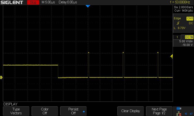
The second shows the same over a long time scale, showing that the output looks like the DC offset of 2.5V for almost 70 ms (!) before the signal kicks in. The "black" area to the right of 70 ms is actually a bunch of narrow output pulses (3.3% duty?) at 70 kHz.
The third waveform is just the signal a while after enabling (looks fine).
John
Is there a possibility to upgrade the bandwith from 40 to 120 by a license key?
The hardware seems to be the same to me.
Looks like someone hasn't read the thread!
Answer: Yes.
There is another output glitch that I have seen. I sent this directly to Siglent back in early February, but never got a response. It seems like they are much more responsive when it shows up here, so here goes:
When enabling a channel, the DC offset appears to be enabled before the pulse output, and intermittently as well. This can be a big problem when you are starting up. I hope this can be fixed.
Siglent is now linked to your post.
Question: which FW version are you using?
Current Version: 1.17R5
http://www.siglentamerica.com/USA_website_2014/Firmware&Software/firmware/SDG2000X-P17R5.rar Generator set at pulse output, low value zero, high value 10V (10Vpp, 5V offset), 3.33% duty cycle, 70 kHz, using Chan 1 out. The generator is driving a 50 ohm load, so one should see a 0-5V pulse.

Here's mine, AWG output set for HiZ and into 1M scope input.
(sorry, not prepared to risk damaging the 50 Ohm inputs in my DSO that's rated to 5V as most 50 Ohm inputs are)

The first waveform triggers when output is enabled. There are a bunch of glitches, and note the amplitude of 2.5V (equal to the expected offset value into 50 ohms).
Not seen any glitches other than the output enable
relay contact bounce.
What will your output look like if you set it for 50 Ohm not HiZ as you should for a 50 Ohm load.

The second shows the same over a long time scale, showing that the output looks like the DC offset of 2.5V for almost 70 ms (!) before the signal kicks in. The "black" area to the right of 70 ms is actually a bunch of narrow output pulses (3.3% duty?) at 70 kHz.
Something's wrong here, the offset while initially being correct is then lost and the following correct waveform is then without the selected offset. No detected glitches
Note in all images the baseline and trigger level settings.
All screenshots taken as single shot trigger setting.
Ok, so the SDG2042X seems to tick most of my boxes but one: floating signal outputs in order to prevent ground loops, and to gain the ability to refer the outputs to an arbitrary potential. From the teardown videos, I do not see huge obstacles to converting the outputs to floating. The control board and the signal board are connected by a short piece of flat flex cable across which all the digital signals are carried. Replacing that with a little intermediate board containing the right ADuM isolators (and perhaps replace the rear panel BNC's with isolated ones, in case they aren't already there) should do the trick, right? Add a few tens of euros to the cost of the instrument, and you have the signal quality of the 2000X series, combined with the floating outputs sported by the 5000 series. That would be great...
I see one possible hurdle though. In the teardown video on the SDG5000 series, I can clearly distinguish the required isolated voltage output for the CPU board on the power supply board. In the teardown video of the SDG2122X, I can see a separate connection for the for the CPU board, but I see no evidence of an isolated supply voltage: the number of output filters is 4 instead of 5, and the transformer used (NT1795NL) is the same as in the SDG1000 series, and this one has no separate CPU board at all. So it looks to me as though the power supply has a dedicated connection for powering the CPU board, this connection is simply an extra parallel connection to a supply voltage that also goes to the signal generator board. Am I right? Could anyone who has voided the warranty on his generator try to find this out or post a picture of the underside of the PSU board? I hope I am wrong...
Detailed photos on the SDG1000 power supply board, which seems to be almost identical to the SDG2000X power supply, can be found here:
https://sigrok.org/wiki/Siglent_SDG1010Here, at 13:55, you can clearly see the isolated CPU board voltage being made on the SDG5000 PSU board:
The CPU board looks quite similar (if not the same) to the one used in the SDM3055 multimeter...
There is another output glitch that I have seen. I sent this directly to Siglent back in early February, but never got a response. It seems like they are much more responsive when it shows up here, so here goes:
When enabling a channel, the DC offset appears to be enabled before the pulse output, and intermittently as well. This can be a big problem when you are starting up. I hope this can be fixed.
Siglent is now linked to your post.
Question: which FW version are you using?
Current Version: 1.17R5
I have the 1.17R5 firmware installed. I understand the glitches are due to a relay, and there is no problem with the offset values, it is never dropped. 0-5V low/high settings are the same as +/-2.5V + 2.5V offset, so I use them interchangeably. Sorry if that caused any confusion.
It looks like internally, the generator does +/-2.5 and then adds an offset, which makes sense to keep all the waveform resolution bits. However, it appears to turn on the offset first, then active the relay, and then finally the pulse. This is not a good order, as now the generator sends this to some circuit under test, in my case a power circuit. By the time the generator output is finally correct, the circuit can be dead.
The circuit under test has a comparator at the input with 2.5 V. Of course we can change it, but should not have to, and 2.5 really the preferred value. Note that we have customers that ask us for recommendations. I would love to recommend the Siglent, and I use it myself. It has a lot of potential, but if it can cause problems with our own stuff, I cannot do that. However, some other bugs got taken care of quickly, so I have hope for this as well.
John
Just wondering why Siglent Europe (siglent.eu) only has available the 15R2 firmware update available for the SDG2042X, but Siglent America has the 17R5 release. Is it something we Europeans have done to upset them or are we destined to be a few releases behind the US?
I'm pretty sure siglent.eu is just a Siglent reseller, not actually Siglents website. The address nctnico posted is Siglents official European website.
