Recent Posts

Pages: [1] 2 3 4 5 6 ... 10 Next
1
Beginners / Re: Automatic golf ball dispenser
« Last post by BTO on Today at 06:14:52 am »
Ok so I simple need to power sources

No.. you SIMPLY need TWO power sources  :P
Yes that's correct, You're very close, Throw in a dedicated power source for the solenoid and test it.
Let me know how it goes

Again this is where you can try using that dual power supply board (MB102) that you bought, (Depending on the requirements of the Solenoid)
2
Beginners / Re: Automatic golf ball dispenser
« Last post by Maclarkson on Today at 06:09:50 am »
Ok so I simple need to power sources
3
FPGA / Re: Analog video output with FPGA ?
« Last post by Jaunedeau on Today at 06:03:16 am »
Didn't you say DAC, not ADC?

The idea is to have both and ADC and a DAC, and use the ADC to calibrate the DAC and build a lookup table to correct the DAC errors. I've found a post about this idea ( https://www.eevblog.com/forum/projects/r-2r-ladder-dac-calibration-what-do-you-think/ ) and when you see the first oscilloscop capture, it seems possible to make a calibration table and get a good 14bit adc from this 16bit R2R adc after calibration.
My case is a bit different : I need 8bit not 16, but about 30Msps not 44ksps. Also since my input is discrete (e.g. the atari 2600 has a 128 colors palette), I could build a calibration table for the 128 RGB triplets instead of three calibration tables of 256 individual R, G and B and compensate for the crosstalk.

I am a software developer, only learning electronics as a hobby, I have no intuition of if this could be a good solution :D (to the problem of video ADCs eventually no longer be available in a few years, and cost reduction because cost reduced projects are more fun to me).
4
Repair / Re: Mig welder wire feeder controller board not working
« Last post by TERRA Operative on Today at 06:00:17 am »
there has got to be a better filter then a foam ear plug. maybe a fine nylon brush?

its such a dodgy construction worker hack

I don't like it because theoretically something can get stuck in the foam and scratch up the wire, and it can soak up grease and smear it on etc. I feel like a nylon brush would brush off debris and result in cleaner wire

there must be a more professional engineering solution to this using better hardware

The 'official' way is a lightly oiled felt 'slug' held on with a metal clip.
https://www.google.com/search?q=mig+wire+cleaner&udm=2


Thank you so much.  I did not expect this sort of information to be available.  When I bought this welder new I did not even get a manual with it.

I think i should be able to do something now, probably let the magic smoke out somewhere. :)

The benefit of buying a quality brand instead of a cheap Chinese no-name import. ;)

And I archived all the manuals from when I was in the welding and cutting equipment repair game.
5
Test Equipment / Re: TinySA Ultra launched
« Last post by erikka on Today at 05:58:50 am »
The tinySA does not do a continuous sweep but sweeps in discrete steps with possible silence in between. Set the scan speed slow and you will see the step
6
General Technical Chat / Re: The strange case of phase angles
« Last post by sicco on Today at 05:49:43 am »
The voltage source has an output impedance of zero ohms. It thus dictates a voltage on both the R, the L and the C. No matter what the values are for R, L or C. So no way that L, C, or R can ‘see’ each-other and form a LC resonator or so.
The phase angle from voltage to current through each component leg is zero for R, 90 and -90 for L and C. The current from the source is the sum of I_R, I_C and I_R. So subtract L and C currents because they are 180 deg apart. Then atan the imag and real. So something like atan((I_L - I_C) /I_R) for the phase difference from V_source to I_source.

7
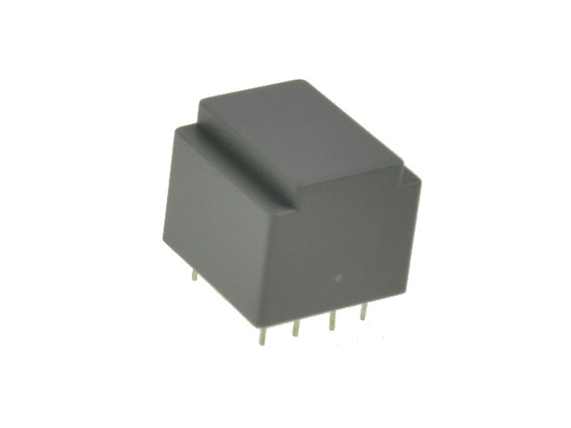
It would be cool if all transformers were held together by easy to remove parts.
But glue solves many problems at once.


I always got rid of these, even if I got their details (from SONY CRTs):
8
FPGA / Re: Analog video output with FPGA ?
« Last post by BrianHG on Today at 05:46:03 am »
Just a random thought but : if I implement on an MCU instead of an FPGA (or use and FPGA that can implement an ADC), could a 9 or 10 bit (instead of the 8 required) bits ADC plus an autocalibration routine at boot be a good solution ?
Didn't you say DAC, not ADC?
9
FPGA / Re: Analog video output with FPGA ?
« Last post by BrianHG on Today at 05:43:23 am »
Hdmi to vga would be an option, and probably what I will do in early stages since I will prototype on tang nano 4k board. One problem that sourcing one that introduce low lag might be a problem on the cheap ones (e.g. one could be good, then they can change the component in the same product). Also some seems to only support full hd, and might cut some cost saving possibilities when I aims only for CGA.

Dedicated DAC seems to be the way to go... I'll use one and hope it stays available in the futur :D
The cheap ones are the ones without any lag.
Do you honestly believe that such a $3-$6 device actually has a DDRx memory chip within to delay the picture by a frame or more, introducing lag?
The only lag in a 3$ device will be a few pixels as the HDMI gets de-serialized, then sent to the dac immediately.

If you are getting lag, it is most likely coming from somewhere else.  Maybe your source video device is attempting to scale the picture to a video mode listed in the converter's EDID?  Hence the delay is not the converter's fault.

Yes, for the supported video modes, a number of devices might not lock onto specific video clock frequencies, basically failing to function.  I listed a review site which tests the old 240p mode used by old gaming systems & CGA.
10
The time you are exposed does make a difference.
If the electric current is enough to contract your muscles and grip that live wire with even greater strength, of course the exposure time is only going to increase.
Pages: [1] 2 3 4 5 6 ... 10 Next