Recent Posts

Pages: [1] 2 3 4 5 6 ... 10 Next
1
Repair / Re: Mig welder wire feeder controller board not working
« Last post by TERRA Operative on Today at 06:00:17 am »
there has got to be a better filter then a foam ear plug. maybe a fine nylon brush?

its such a dodgy construction worker hack

I don't like it because theoretically something can get stuck in the foam and scratch up the wire, and it can soak up grease and smear it on etc. I feel like a nylon brush would brush off debris and result in cleaner wire

there must be a more professional engineering solution to this using better hardware

The 'official' way is a lightly oiled felt 'slug' held on with a metal clip.
https://www.google.com/search?q=mig+wire+cleaner&udm=2


Thank you so much.  I did not expect this sort of information to be available.  When I bought this welder new I did not even get a manual with it.

I think i should be able to do something now, probably let the magic smoke out somewhere. :)

The benefit of buying a quality brand instead of a cheap Chinese no-name import. ;)

And I archived all the manuals from when I was in the welding and cutting equipment repair game.
2
Test Equipment / Re: TinySA Ultra launched
« Last post by erikka on Today at 05:58:50 am »
The tinySA does not do a continuous sweep but sweeps in discrete steps with possible silence in between. Set the scan speed slow and you will see the step
3
General Technical Chat / Re: The strange case of phase angles
« Last post by sicco on Today at 05:49:43 am »
The voltage source has an output impedance of zero ohms. It thus dictates a voltage on both the R, the L and the C. No matter what the values are for R, L or C. So no way that L, C, or R can ‘see’ each-other and form a LC resonator or so.
The phase angle from voltage to current through each component leg is zero for R, 90 and -90 for L and C. The current from the source is the sum of I_R, I_C and I_R. So subtract L and C currents because they are 180 deg apart. Then atan the imag and real. So something like atan((I_L - I_C) /I_R) for the phase difference from V_source to I_source.

4
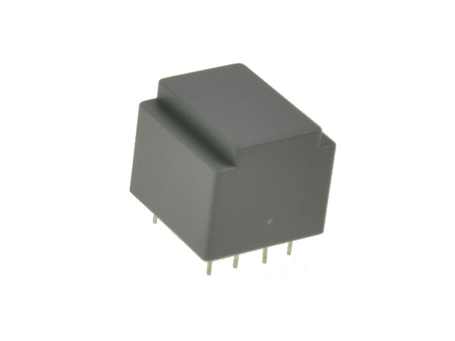
It would be cool if all transformers were held together by easy to remove parts.
But glue solves many problems at once.


I always got rid of these, even if I got their details (from SONY CRTs):
5
FPGA / Re: Analog video output with FPGA ?
« Last post by BrianHG on Today at 05:46:03 am »
Just a random thought but : if I implement on an MCU instead of an FPGA (or use and FPGA that can implement an ADC), could a 9 or 10 bit (instead of the 8 required) bits ADC plus an autocalibration routine at boot be a good solution ?
Didn't you say DAC, not ADC?
6
FPGA / Re: Analog video output with FPGA ?
« Last post by BrianHG on Today at 05:43:23 am »
Hdmi to vga would be an option, and probably what I will do in early stages since I will prototype on tang nano 4k board. One problem that sourcing one that introduce low lag might be a problem on the cheap ones (e.g. one could be good, then they can change the component in the same product). Also some seems to only support full hd, and might cut some cost saving possibilities when I aims only for CGA.

Dedicated DAC seems to be the way to go... I'll use one and hope it stays available in the futur :D
The cheap ones are the ones without any lag.
Do you honestly believe that such a $3-$6 device actually has a DDRx memory chip within to delay the picture by a frame or more, introducing lag?
The only lag in a 3$ device will be a few pixels as the HDMI gets de-serialized, then sent to the dac immediately.

If you are getting lag, it is most likely coming from somewhere else.  Maybe your source video device is attempting to scale the picture to a video mode listed in the converter's EDID?  Hence the delay is not the converter's fault.

Yes, for the supported video modes, a number of devices might not lock onto specific video clock frequencies, basically failing to function.  I listed a review site which tests the old 240p mode used by old gaming systems & CGA.
7
The time you are exposed does make a difference.
If the electric current is enough to contract your muscles and grip that live wire with even greater strength, of course the exposure time is only going to increase.
8
Please keep me updated because I'm really interested, I have been looking for such project and would be lovely to give it a go!
9
Beginners / Re: 555 driver and Transformer questions
« Last post by Andy Chee on Today at 05:30:01 am »
can you explain to me what to look for in the schematic that shows a strong DC offset?
Examine the output driver stage that is connected to the transformer winding.

Imagine the switching device/transistor/MOSFET/IGBT/relay is permanently on, or running at high duty cycle, say 99.99%

The voltage across the transformer in such a scenario, is effectively DC.  Not all transformers are tolerant of DC, and will result in saturation of the core.  Practically this means the core will heat up, and power will no longer transfer to the secondary winding (or less power anyway).  Also once the core saturates, your switching device will effectively be switching a dead short circuit, which will kill most devices, depending on power level.

If you change the duty cycle to 50%, your circuit will still pump DC into the transformer winding, but at 50% voltage.  This may still be plenty enough to saturate the core.

In summary, you need an alternative circuit topology.

The traditional alternate topology is a centre-tapped transformer with each winding being driven push-pull.  Given you lack a centre-tap, you'll have to go with a H-bridge configuration.  Or if you have a bipolar supply, you can push-pull using that.

Finally, you could try a large 1000uF non-polarised capacitor* in series with your transformer winding.  This circuit topology is simple, but generally low power.

(*they're hard to find, so use 2x 2000uF polarised capacitors in series, with polarities reversed back-to-back)
10
Beginners / Re: Automatic golf ball dispenser
« Last post by BTO on Today at 05:27:50 am »
Ok so moving on to the problem. I managed to get something working. I connected up a sound sensor module the Arduino, power, and a relay module. What’s the best way to connect the solenoid to the same battery via the other side of the relay. See pictures. Problem is the solenoid obviously drains too mush current. Because the leds on the Arduino take a dive. How should I best connect up the solenoid?

Quote
Ok so moving on to the problem
Yes, Lets get back to Golf and Electronics  :P

Quote
What’s the best way to connect the solenoid to the same battery via the other side of the relay. See pictures. Problem is the solenoid obviously drains too mush current. Because the leds on the Arduino take a dive. How should I best connect up the solenoid?
- This is a very commonly experienced problem, Your idea is to use the main power source for everything. it won't work very well.
THE SOLUTION IS...  The Solenoid needs it's own power supply which has to go through a relay and that relay will receive a signal from the Arduino,  No doubt the condition that has to be met for the relay to get the signal to be energized is that the sound sensor has to experience
a certain condition or state
DOES THAT HELP ?
Pages: [1] 2 3 4 5 6 ... 10 Next