Nice job. Can you point me to an image compiled without those changes and one with the changes?
To get an image without any of the changes just follow the steps of building the image of unframework, so my steps in the buildroot readme.txt file without changing any of the files. Well the changed one is in the repository.
And well done to iscle on getting the display up and running. What did you to to get that done?
Is it this section that needs to be changed?
panel: panel {
compatible = "lg,lb070wv8", "simple-panel";
#address-cells = <1>;
#size-cells = <0>;
enable-gpios = <&pio 4 6 GPIO_ACTIVE_HIGH>;
power-supply = <®_vcc3v3>;
port@0 {
reg = <0>;
#address-cells = <1>;
#size-cells = <0>;
panel_input: endpoint@0 {
reg = <0>;
remote-endpoint = <&tcon0_out_lcd>;
};
};
};
And well done to iscle on getting the display up and running. What did you to to get that done?
Is it this section that needs to be changed?
Yes, just replace "lg,lb070wv8" with "innolux,at070tn92" and it will work

Ok I will try that.
As you seem to know your displays any idea on this:
I received the display I bought (https://nl.aliexpress.com/item/32691414835.html?spm=a2g0s.9042311.0.0.27424c4dER5LsR) but it does not work with the FNIRSI-1013D. It shows some white fading and stabilizes in a blue bar on the right side of the display.
On the cable there is "7300130906 E231732 NETRON-YF P08 94V-0\1332"
I made a video of what it does and posted it on youtube (https://youtu.be/K5SbKid2z_o)
This is very similar to what happened on the Fnirsi LCD before setting that setting correctly. It's a timing issue, fixing the timing parameters will make it work. Do you have a datasheet for it?
PD: A quick search shows it is a 1024x600 instead of 800x480
Yes, that version works for me with the reset trick!
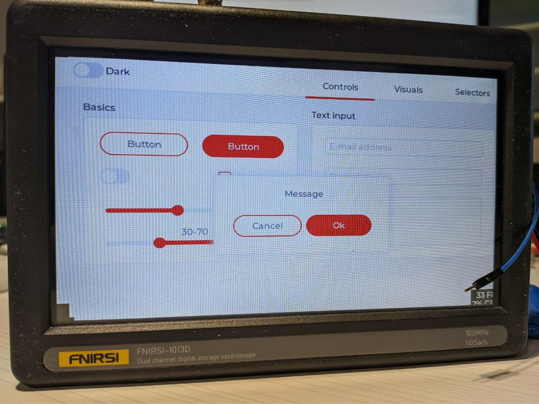
Edit: A small LVGL demo running! Of course, no touch...
Nice, but without the fpga interface it is just a small linux computer

Next up is getting the console to be on the usb interface. For this we have to check out thirtythreeforty's work on his business-card. When that is running the touch can be programmed. Should not be to hard to write a bit bang I2C driver for it.
Did not get much done on the proof of concept about ser8989's thought on how to reverse the touch panel's coordinates. Read and compared the configs of both the old and the new panel and they are the same. It is not an exact match with the byte string found in the program, but fragments do, so it might be what is used to send to the panel, or it might not be.
Need to write code for the stm32 to handle both i2c interfaces under interrupt and do the translation. Not to complex, but with the linux stuff on the side it slowed down, so maybe tomorrow

It's very easy to reverse the coordinates when writing a linux driver, it's just a conditional (although, if it can be done in the IC, that's one less branch that the CPU has to worry about).
Once we get usb uart, I'll begin to code the touch driver.
This is not a concept because I have already tested it, you have the same configs in the old and new panels because when you start the firmware config is written to the panel, but this happens only on the English version of the firmware, but in the Chinese version config is not overwritten. The entire config is missing in the firmware because in fact the config is several independent data structures.
By the way, I got an oscilloscope with a dead vertical bar on the touchscreen, was broken (defective), one of the channels ITO gt911, I was able to find a replacement only gt915, pinout and features they are the same based on the datasheet, but in default configuration, ITO channels gt915 are in reverse order so the touchscreen works in a mirror mode, reconfiguration of channels and use the Chinese version of the firmware corrects this situation. The easiest way for those who have the touchscreen with gt915, find and solder gt911 (at the moment I managed to find and gt911). But to find and fix the part of the code that is engaged in reconfiguration for me is a matter of principle.
I was wondering about the differences between the two GT ic's. According to your findings it is that the sensors are scanned in reversed order and therefore the order has to be changed in the configuration. For me de-soldering and re-soldering the GT ic's is not an option. To small and fragile. It is also the question if on the defective panels it is caused by the ic or by the ITO.
For the code changing it depends on the config checksum that needs to be correct. When it is just a sum of the bytes, then the order of the sensor numbers will not matter and a simple change of the binary might do the trick. (Maybe you already tried it) Otherwise, if the software does not do this itself, it involves calculating a new checksum and changing that byte also.
Does yours show the same reversal of the coordinates when you connect it to the scope?
I received a wire the other day for separating the screen. When replacing the touchscreen, I found the following feature. Initially, after the experiments, I had the firmware installed from the forum (
https://1drv.ms/u/s!Av-Riptwsak2iskn0CO56k7NHOOyzg?e=lBgubm) The touchscreen works absolutely correctly on this firmware. But I decided to return the stock firmware (
https://1drv.ms/u/s!Av-Riptwsak2iskpuqmWeb7_qvBy2g?e=7FLSUm) - the touchscreen works in reverse on this firmware! Interestingly, the stock touchscreen works the same on the stock firmware and on the firmware from the forum - not reversible
And were you able to revert back to a correct working system or did you end up like eljot and me with a reversed touch system. If I have a correct understanding of it all, once the configuration has been written to the new touch screen it holds on to it. This means that it is non volatile. I did see something about flash in the datasheet or programming manual, but it is a bit obscure.
But no worries, we (iscle, ser8989, I and maybe others) will find the solution. It takes time since we are trying multiple things, like making linux operational for open source scope-ware, either with the original fpga or an fpga config or our own (this is an option but takes more of an effort. Is another of my interests). The other path is find out how to change the binary that it works with the other touch screen.
I'm looking into thirtythreeforty his work for the console to usb, but he only did it for the linux part. He did not remove the bindings to uart0 in u-boot and linux, so it looks like his version still boots on uart0 and for the linux part maybe using both as communication path. His version of u-boot is newer than what we are using now and looks like stuff has moved to other locations, so would have to find the correct files to edit. I will stick to the older version for now.
I did find settings for u-boot to make it use usb as console interface, but not sure if it will work. So will test this first.
And were you able to revert back to a correct working system or did you end up like eljot and me with a reversed touch system.
It was no longer possible to return to the correct operation of the touchscreen

. Now the touchscreen works in reverse on any firmware. Which is very strange
, since I was writing the firmware to the memory chip by completely removing it from the board and also disconnecting the touchscreen loop. It seems to me that there is a code in the oscilloscope firmware that changes something in the touchscreen firmware.
I also downloaded the firmware from another oscilloscope (
https://1drv.ms/u/s!Av-Riptwsak2ithz1mLIZsvK0lsp9Q?e=hZYflj). On it, the touchscreen also works in reverse, but the screen image is also shifted on it.


" alt="" class="bbc_img" />
The touch screen gets the config the moment you start the scope with the stock firmware. In the GT911 (GT9157) there is a register that tells the touch panel to save the configuration, if it is newer than the previous one. The scope writes a 1 to this register meaning it should store the config. You can probably use an arduino (make sure to not use 5V on the touch panel) to write a reversed configuration like ser8989 suggested to your panel and load your scope with the old firmware and it should work as before.
Did not test this myself. Tried reading my flash chips just now and it did not work with my programmer
. It is a CH341 programmer and for some reason it does not work. It lifts the voltage on the flash chip to 4.1V when connected to the chip. (No power on the scope itself, since there is a diode in the flash power line) So need to investigate that also.
You can probably use an arduino (make sure to not use 5V on the touch panel) to write a reversed configuration like ser8989 suggested to your panel and load your scope with the old firmware and it should work as before.
It will be fun to try. But where can I get an Arduino sketch?
I wanted to download the GT911 dump. But I could not find information anywhere how and with what programmer it is possible to do this
Found just this
http://andr7e.blogspot.com/2015/05/c-goodix-gt9xx.html
Might be that ser8989 wrote one. But should not be that difficult to write one your self. I do not have arduino ide installed at the moment, so can't do it for you.
When you have a STM32F103C8T6 bluepill board I can write code for that.
In the file are the bytes being written from the scope, starting at register address 0x8047, to the touch panel. This is the wrong setup for the new panel. Needs to be changed like ser8989 described some posts back.
The other file is changed to hopefully match what ser8989 described. The checksum is based on a summing algorithm so should not suffer from changing byte order.
When you have a STM32F103C8T6 bluepill board I can write code for that.
I do not have this board, but I can buy it
See my previous post for handy stuff.
The board you ordered has the CS chip on it. Not a problem, but for programming an other chip ID needs to be used. I use openocd under linux for the programming. Will add the correct config for the CS chip too.
 , but finding the timings how does one go about? Lots of trying?