That's a bloody Nippon Chemicon! Check to see if it still works.
I will sure check, but being a novice, I am not sure if you mean they are "indestructible" or "gold plated"

and if they work, should I leave them as they are because of their brilliant reputation; or should I replace them? Bear in mind that they are 50 years old and even if they still work, should I trust them to continue to work and for how long?
Nippon Chemi-chon capacitors have excellent reputation for durability. Despite this, the particular dielectric technology can have a limited lifespan regardless of the brand.
I hate replacing parts without need, but it is very difficult to properly test this capacitor throughout its voltage range of 1.5kV - you never know if it has a leak that manifests itself only after a specific voltage.
All in all, if you can spare the time you can leave the capacitor, repair everything else, reassemble the unit and test it - if it works well you leave it there but if it doesn't you have a suspect.
Hey all,
I was unsoldering some components off a board and "scored" 4 nice looking optocouplers while doing it. However, I'm having a hard time finding a data sheet for them. The numbers are easily readable but the only letter of the name I can clearly make out is the F at the beginning. It looks kinda like
FyyD,
FyyN, or from a distance it looks like
Fury. The are all marked 735 in front and 6E in back. Anybody have any idea what they are? And maybe a data sheet or link to one? It would be much appreciated.
Thanks in advance!
Rob
Hi.
Might be a silly question but, are you sure they are opto's?
Hey all,
I was unsoldering some components off a board and "scored" 4 nice looking optocouplers while doing it. However, I'm having a hard time finding a data sheet for them. The numbers are easily readable but the only letter of the name I can clearly make out is the F at the beginning. It looks kinda like FyyD, FyyN, or from a distance it looks like Fury. The are all marked 735 in front and 6E in back. Anybody have any idea what they are? And maybe a data sheet or link to one? It would be much appreciated.
Thanks in advance!
Rob
Not an F, it's in japanese and says Moririca (Moririca Electronics Ltd) and according to Google it is a optocopler and called MCD735, but that is all I can find on the net with my five minute search.
/stefan
Hi.
Might be a silly question but, are you sure they are opto's?
Yes without a doubt. I have other optos just like it. You can look at the legs and tell the LED on one side and the CDS on the other.
Not an F, it's in japanese and says Moririca (Moririca Electronics Ltd) and according to Google it is a optocopler and called MCD735, but that is all I can find on the net with my five minute search.
/stefan
Ah OK. Thanks. I typed all kinds of things in google. I would have never thought it might be Japanese writing.
In every CRT monitor or TV I have taken apart, there was this odd inductor that has a permanent magnet glued to it. Is that to offset the magnetic field generated by a DC bias current so a cheaper core can be used?
Yes, that's what it's for, the permanent magnet biases the inductor to oppose the DC current so a smaller, cheaper core can be used.
Might be, but might also be line linearity correction. Magnet causes the inductor to saturate in one current direction only, giving more current on that side of scan. Some have a rotatable magnet for adjustment.
Those look like LDR (light dependent resistor) type, driven by a visible LED. The LED pins are the thick ones and the LDR the thin ones.
Try applying current to the LED (correct polarity) over a 0-20mA range and monitor the LDR pins on the Ohms range of your DMM. If you see a varying resistance which is the same when you reverse the connections then it is an LDR.
They're useful for control of AC signals, for instance, volume controls or amplitude feedback in a low distortion Wein Bridge oscillator. Here's a generic app note:
http://www.perkinelmer.com/CMSResources/Images/44-3429APP_AnalogOpticalIsolatorsAudioApps.pdfTry looking up Vactrol too, I think they make them.
P.S. Once you have an idea of the resistance range then you probably don't care much about the specific datasheet. But don't go above 20mA on the LED.
Yeah. Like I said I definitely know what it is. I have tested it. I just cant read the name so I can download the data sheet .pdf, that's all.
Thanks!
I forgot to mention the acronym LDR. LDR is a CDS Photoresister.
Looks like you might have to do specs measurement yourself. Can't seem to find a readable datasheet either

In every CRT monitor or TV I have taken apart, there was this odd inductor that has a permanent magnet glued to it. Is that to offset the magnetic field generated by a DC bias current so a cheaper core can be used?
Yes, that's what it's for, the permanent magnet biases the inductor to oppose the DC current so a smaller, cheaper core can be used.
Might be, but might also be line linearity correction. Magnet causes the inductor to saturate in one current direction only, giving more current on that side of scan. Some have a rotatable magnet for adjustment.
What did I miss about this 6 years old post resurfacing?
Even though the comment is perfectly pertinent.
No worries, glad it helped.
Hi!
Found the mystery component in an intercom system, and none of us could figure out what it is. The one we can't figure out is the 4-pin, white thing next to the 8-pin smd relay between the two resistors (the board has two identical setups on either side). The silver-colored stuff in the middle reminded me of an LED, with two asymmetrical halves separated by a narrow gap, but that wouldn't make sense. The function of the board is to switch a microphone signal and ptt-button signal from one input to one of two radios depending on the position of an external switch.
Hope my explanation is not too confusing, being quite exhausted after over 20 hours of work on the intercom system...
It quite clearly is, despite serving no apparent reason in there... Thank you!
Sometimes LEDs are used as low voltage zener diodes (zener diodes below 4V typically have a very soft transition, LEDs have a much steeper current slope).
But in this case based on the position next to the relay I would assume they show the active relay.
My guess was also to show which relay is active, but being mounted under another board in an IP67 box, they can't be seen once the box is mounted (which has to be done before connecting the external wiring). But then again this whole rats nest was made by a "professional" company specialized in communications systems, so who knows what they were thinking...

Being desperate to find spares for this
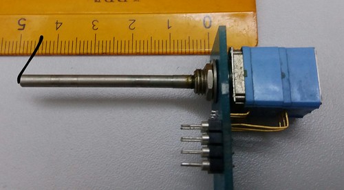
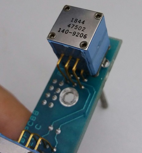
it's a dual gang potentiometer... with endless rotation! used in lecroy test equipment
Hi all,
Everyone in the world has seen these but I've been googling stuff like "Power Cable' Safety Clip, Security Clip, Cable Stop, Pull Stop, etc. and can't find what I'm looking for. I've destroyed at least 50 of these with pliers and a flat head over the years. I'm kinda embarrassed I don't know what they are. (See pic)
So I got a couple questions:
1) What are they actually called?
2) Whats the best way to open/remove them?
Thanks in advance!
Rob
They are called strain reliefs. There are special pliers made for installing and removing them, though being cheap I've had success using a big end nipper.
-Pat