-
Large area silicon chip with bond wires. Applications are sensing in things like industrial equipment to detect alignment, or other applications which were use once.
-
What connector is this? Some type of coax...
http://th03.deviantart.net/fs70/PRE/i/2013/316/a/4/connector_by_phaedrus2401-d6u1cyp.jpg
I need a 100Mhz 10x scope probe with that connector, and BNC on the other end. Don't know what to call it to search for it. -
It looks like an RP-SMA connector .As used in wifi .
-
Thanks,
I think smaller versions of that are used in cd/dvd/blueray players.. not 100% on that though
any idea where I get something like that? I also wondered, how are you so sure. In what kind of application have you seen something like that before?
Thanks
-
What connector is this? Some type of coax...
http://th03.deviantart.net/fs70/PRE/i/2013/316/a/4/connector_by_phaedrus2401-d6u1cyp.jpg
It's just a standard male SMA connector, RP-SMA swaps the pin to the other side of the connection.
Yes it is.My bad

-
I have never seen a JFET used like that before. I wonder if they are using it as a Schottky diode.Anyone know what the FET labelled E401 is (second schematic). It's in the peak detector circuit and it looks like the drain and source are shorted together.
Looks like a standard N-channel JFET being used as a diode for clip detection. If you tie the drain and source together the JFET also works similar to a diode, except you have one P-region and two N-regions.
Is it maybe used as a variable resistance device? Anyone know a substitute or part number?
BTW This is a very nice voltmeter with plenty of rectification options and bandpass filter selections. Perfect for audio work really (or anything to 500 KHz).

Though it's built with standard components, this ac voltmeter contains many features not typi-cally found in commercial meters; the most unusual is a selection of rectification modes. The meter responses available include true RMS ('fRMS), average, RMS-calibrated average responding, positive peak, negative peak, positive-peak hold, and negative-peak hold.
High- and low-pass filters (S1 and S6, respectively) allow the -3-dB-passband to be varied from as little as 10 Hz to 200 Hz, to as wide as dc to 500 kHz. The low-pass filter also is effective in the 100x amplifier mode, where the input equivalent noise level is only 0.3 pV, with 10-kHz roll-off.
(NOT WRITTEN BY ME)
What I find interesting is that the part number is not called out while every other part on both schematics is clearly labeled as to what the specific part number is or at least the value. Instead, for that part they apparently used the PCB part identifier label. That seems rather odd and possible a clue as well.
I just came across this new topic today: What does this JFET circuit do?Anyone know what the FET labelled E401 is (second schematic).
Well I guess it is an E401. Maybe at the time it was a good choice for use as a low leakage diode, maybe it or a similar JFET still is.
I found LS841 listed as an equivalent. Searching will turn up a datasheet for that, strangely it is a dual n-channel JFET.
If you are trying to re-create this circuit you just need a low leakage diode or JFET used as one. The LS841 gate leakage is specified at 50pA max, 25C and 20v so that's a target to match.
www.eevblog.com/forum/projects/what-does-this-jfet-circuit-do/
JFETs were used in the same Source-Drain short circuited configuration in HP 3456A 6½ Digit Digital Multimeter as input protection diodes connected to Vcc and Vee as you can see in the service manual posted in that topic.
This Burr-Brown (now TI) application note mentioned in that topic explains why and how to use JFETs as diodes:
DIODE-CONNECTED FET PROTECTS OP AMPS www.ti.com/lit/SBOA058
Basically it's because JFETs have much lower leakage current than PN-junction devices like diodes and BJTs normally has, like Rufus mentioned. -
Hey all!
I'm helping a local non-profit build up a few arcade cabinets they had donated to them in various states of working. I already fixed up their copy of NFL Blitz 99 (Go Bears!), and the kids requested I get going on Tekken 2, and I don't blame them.
I've got the cabinet in my shop, and I've gotten it fixed up through the ROM board (get a masculine "GOOOOD MORNING!" every time I plug it in now), but the CRT works very intermittently. Checked the internals, and, thankfully, the anode discharge resistor is still working, and everything looks pretty good up until that, but then I noticed a component near the power-supply that didn't look right:
I'm betting that's why the CRT only comes on intermittently. There may be more, but I have no idea where to go once this thing gets ID'd and replaced. I've got good tools, though, and have faith in myself, but what the hell is this?

Thanks in advance! Will keep the thread up-to-date with results.
Also, this has been a pretty fun project so far, and I'd like to build up the habit of documenting my work to share, any resources for starting a new thread? -
Please measure the resistance between both "0V" taps. It might be an autotransformer (one winding, no isolation).
-
Oof! It's out of range for my Fluke 179, so beyond 50 M? - Is that indicating that there isn't a short?
-
Oof! It's out of range for my Fluke 179, so beyond 50 M? - Is that indicating that there isn't a short?
It's probably a 1:1; 115 V; 1 A isolation transformer.
On the multiple voltages side only the 0 V an 115 V terminals has been soldered, same voltages as on the other side, so it has been used in 1:1 mode.
What ac voltage do you measure on the between 0 V an 115 V terminals the output side when you put 120 Vac mains voltage on the 0 V an 115 V input terminals?
Doesn't look like anything is wrong with this to me.
And with an intermittent fault, I really doubt this isolation transformer is what causes the fault.
But if the transformer is broken you should be able to replace it with any standard 115 V or 120 V 1:1 isolation transformer with a 115 VA (115 V * 1 A) or higher rating.
Like these two 130 VA and 135 VA examples from Mouser:
http://www2.mouser.com/ProductDetail/Triad-Magnetics/VPS230-570/?qs=%2fha2pyFaduhOD0jibV2nm8lnZ4UdaxDociGravMI74YJ9J53fBGaVA%3d%3d
http://www2.mouser.com/ProductDetail/Hammond/169TS/?qs=%2fha2pyFadug3UFJw%252bR6Egr5Hadcx0iEbk%252be6%252bvco6Ok%3d -
This wouldn't happen to be from a Williams pinball machine or other arcade game would it?
-
This wouldn't happen to be from a Williams pinball machine would it?
No, he wrote Tekken 2.
http://www.arcade-museum.com/game_detail.php?game_id=10060
-
Google search 3P87 transformer takes to http://www.arcade-museum.com/manuals-videogames/P/Playchoice-Ctop.pdf in parts list. Schematic shows 'isolation transformer'.
-
Oof! It's out of range for my Fluke 179, so beyond 50 M? - Is that indicating that there isn't a short?
What ac voltage do you measure on the between 0 V an 115 V terminals the output side when you put 120 Vac mains voltage on the 0 V an 115 V input terminals?
I'm getting the full 120VAC, which would make sense if it's working. I guess I'm gonna back-trace through the rest to make sure the full voltage is coming through (only had 65V through the two original leads). So what is this unit doing? Cleaning/stabilizing the AC?Google search 3P87 transformer takes to http://www.arcade-museum.com/manuals-videogames/P/Playchoice-Ctop.pdf in parts list. Schematic shows 'isolation transformer'.
Thank you!Oof! It's out of range for my Fluke 179, so beyond 50 M? - Is that indicating that there isn't a short?
It's probably a 1:1; 115 V; 1 A isolation transformer.
On the multiple voltages side only the 0 V an 115 V terminals has been soldered, same voltages as on the other side, so it has been used in 1:1 mode.
If the transformer is broken you should be able to replace it with any standard 115 V or 120 V 1:1 isolation transformer with a 115 VA (115 V * 1 A) or higher rating.
Like these two 130 VA and 135 VA examples from Mouser:
http://www2.mouser.com/ProductDetail/Triad-Magnetics/VPS230-570/?qs=%2fha2pyFaduhOD0jibV2nm8lnZ4UdaxDociGravMI74YJ9J53fBGaVA%3d%3d
http://www2.mouser.com/ProductDetail/Hammond/169TS/?qs=%2fha2pyFadug3UFJw%252bR6Egr5Hadcx0iEbk%252be6%252bvco6Ok%3d
If it's outputting the full 120VAC, I'm trusting it's not the headache. -
So what is this unit doing? Cleaning/stabilizing the AC?
An galvanic isolation transformer isolates the electronics from the mains supply for safety reasons. Read more here: https://en.wikipedia.org/wiki/Isolation_transformer
Repairing and working on electronic devices connected to mains voltages should always be done behind an external isolation transformer anyways, also for safety reasons in case you touch a live wire.
Intermitten faults in vintage electronics is often caused by soldering joints that has gone bad or dried out electrolytic capacitors.
Have you tried tapping components and PBCs with the handle of a screwdriver or use diagnostic freeze spray and a blow dryer to provoke the intermittent fault?
These are the most common tools for locating intermittent faults in electronics.
-
I couldn't find these connectors. Are they same type?
GenRad Capacitor standard http://goo.gl/A55QCM
Fluke A55 Thermal Converter http://goo.gl/8Ou6tg
Thanks -
The first link shows some form of shielde 2 pin connector and the second link to the gen rad cap shows what looks like a female Belling-Lee connector.
-
The Genrad one is a General Radio connector-----they're even older than Belling Lee connectors!
Very good,but quite large.
I have seen the 2 pin one around somewhere---probably on a Fluke accessory! -
The seller of thishttp://bit.ly/1fusf3k think it is a sure GenRad 874 connector.
Still looking for information on how to connect a Fluke A55 to a DMM or RT.
-
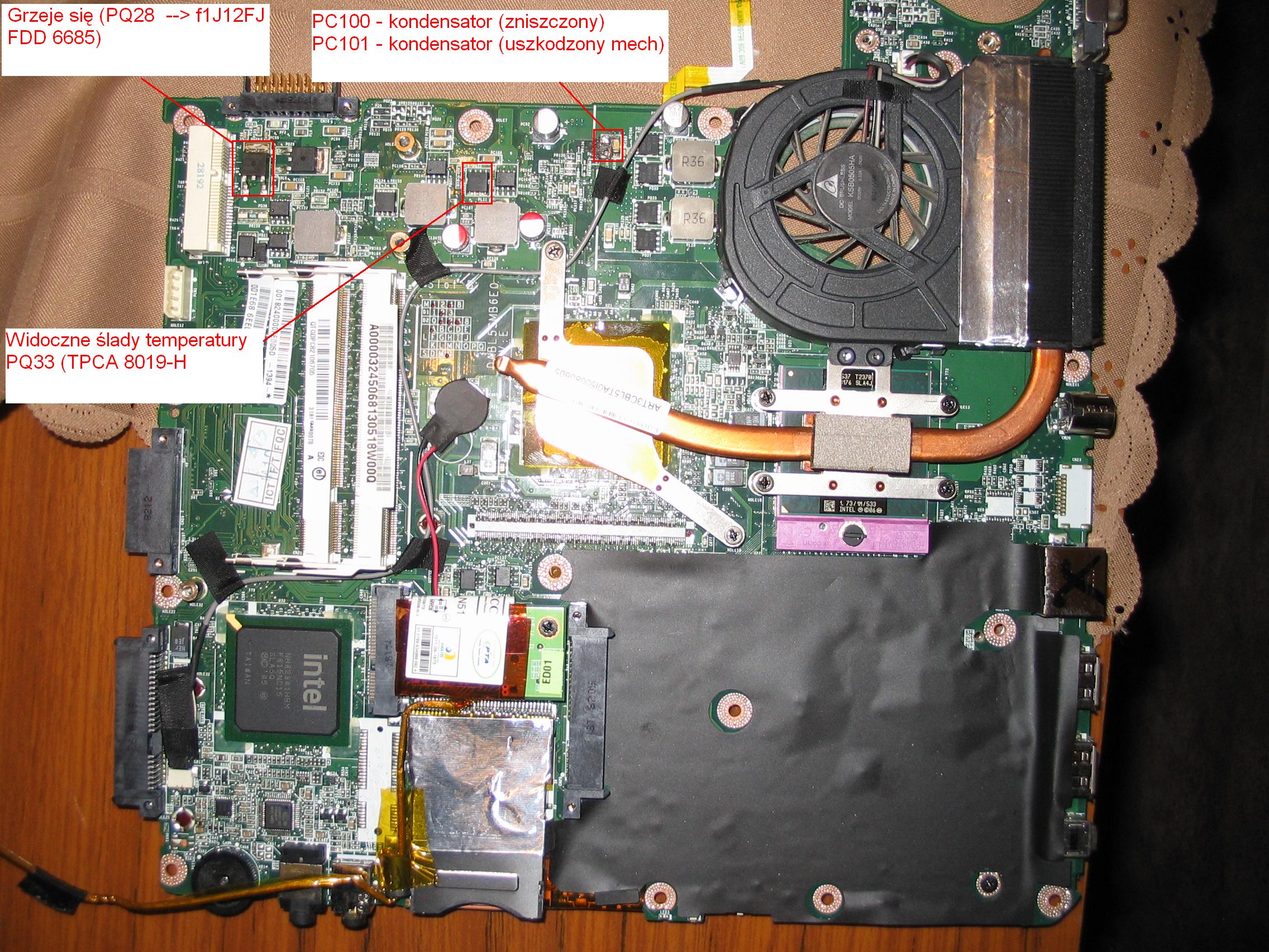
I'm attempting to fix my mums Toshiba laptop that only switches on intermittently (like 1 in 20 attempts) and the battery doesnt charge.
I have come across a bit of an anomaly with a couple of devices that are involved with the battery charger cct that look like 3 terminal regulators but have odd voltages if that is what they are. One has 19v on the case and RH pin and 0 on the LH pin, and the other has 12.6V on the case and 19V on the 2 pins?.
The parts are marked as Fairchild 1J20CB, but I cant find any reference to them anywhere.
Any help?
Allan
-
The parts are marked as Fairchild 1J20CB, but I cant find any reference to them anywhere.
You're looking at the wrong part of the text.
It says:
1J20CB
FDD
6685
So it's a Fairchild FDD6685 30V P-Channel PowerTrench MOSFET: http://www.fairchildsemi.com/pf/FD/FDD6685.htmlQuote**Package Marking Convention
Fairchild Packaging - Top Mark Search for FDD6685: http://www.fairchildsemi.com/topmark/#search/FDD6685
Line 1:$Y (Fairchild logo)
&Z (Plant Code)
&3 (3-Digit Date Code)
&K
Line 2:FDD
Line 3:6685
Here's a better picture of one: http://www.ebay.com/itm/360492328840
It's probably part of a switched mode power supply, so you can't just count on measured DC voltages but need to measure the signals with an oscilloscope.
But I'm not sure if the one next to it that looks burned it is the same part number. It could also be a complimentary N-channel MOSFET instead. Can't see what the part number says on that one. The best way to find out is to trace the MOSFET gates back to the SMPS-driver IC and check the datasheet for that IC.
Looks like one had a similar problem with a Toshiba laptop here (text in Polish): http://www.elektroda.pl/rtvforum/topic2192501.html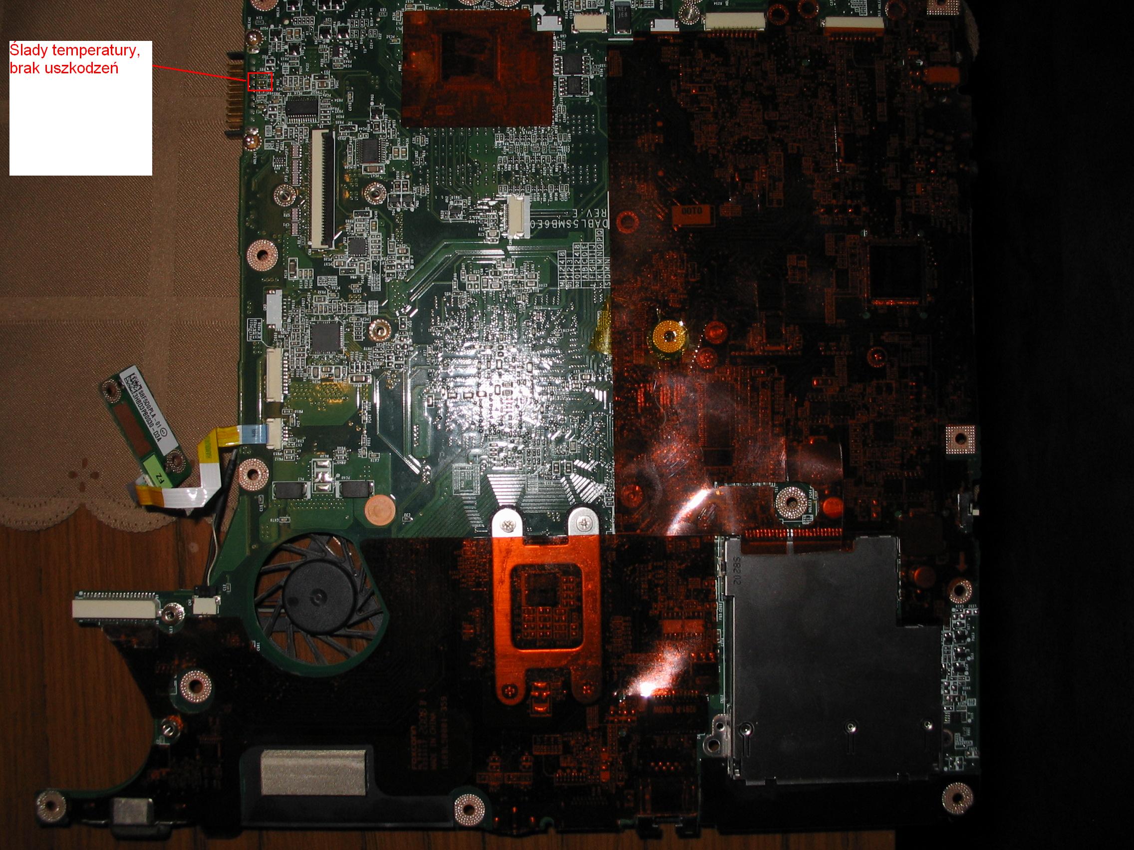
And another one: http://www.elektroda.pl/rtvforum/topic1415016.html
And another Toshiba laptop power supply repair with schematic.
Check the Toshiba laptop switched mode power supply schematic here: http://www.elvikom.pl/forum/viewtopic.php?lang=en&f=209&t=10789 -
Wow thanks AnderAnd.
I thought I had already tried looking for the bottom number with no results and the top number at least gave me a vague possibility. Anyway shows my lack of experience.
Thanks very much for the links, I have translated some of them and they will be quite useful once I get to understand it a bit more. -
Check for dry joints on LOPT (Flyback transformer) also could be a faulty LOPT, dry joints on main output transistor, chopper transistor, do you get retrace lines at all or any field collapse? Any faint raster on screen when it goes off?
What monitor is it, hantarex, wells gardner, electrohome?
It's not that transformer, as stated it's that's a isolation transformer. I bet it's dry joints or LOPT.Oof! It's out of range for my Fluke 179, so beyond 50 M? - Is that indicating that there isn't a short?
It's probably a 1:1; 115 V; 1 A isolation transformer.
On the multiple voltages side only the 0 V an 115 V terminals has been soldered, same voltages as on the other side, so it has been used in 1:1 mode.
What ac voltage do you measure on the between 0 V an 115 V terminals the output side when you put 120 Vac mains voltage on the 0 V an 115 V input terminals?
Doesn't look like anything is wrong with this to me.
And with an intermittent fault, I really doubt this isolation transformer is what causes the fault.
But if the transformer is broken you should be able to replace it with any standard 115 V or 120 V 1:1 isolation transformer with a 115 VA (115 V * 1 A) or higher rating.
Like these two 130 VA and 135 VA examples from Mouser:
http://www2.mouser.com/ProductDetail/Triad-Magnetics/VPS230-570/?qs=%2fha2pyFaduhOD0jibV2nm8lnZ4UdaxDociGravMI74YJ9J53fBGaVA%3d%3d
http://www2.mouser.com/ProductDetail/Hammond/169TS/?qs=%2fha2pyFadug3UFJw%252bR6Egr5Hadcx0iEbk%252be6%252bvco6Ok%3d -
SMD Diode identification, EPP 47 is all that's marked, Becker Indianapolis BE7920
Picture attached, was taken with mobile phone, do not have a digital camera handy.
https://www.dropbox.com/sc/krzm94a01vecd4o/qermgHRZSY -
Ok I need help with this one. I got a Fluke 83 series I in auction that won't turn on. I had almost given up having checked all the usual stuff like fuses etc which are all fine. Until tonight I was bored checking random part values and noticed there was only 68ohms resistance between the positive and negative battery terminals. Hmm I wonder why it wouldn't start. After removing several items that tested bad in circuit, but were fine out of circuit, I came across this. It's clearly bad (roughly 50 ohms across every terminal), I am guessing that it is a bjt of some sort but my googlefoo is failing me. I apologize if it's easy but my laptop is off for warranty repairs so I'm limited to phone searches. The item doesn't have a designator number on the silk screen but it was located top right beneath the LCD.

Thanks guys and gals for your help. Hopefully I can save another device from the trash can.
Sent from my EVO using Tapatalk