N Channel enhancement mode Mosfet.
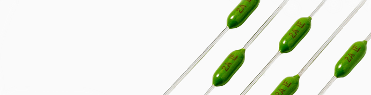
Here are two blown fuses from a device I'm repairing. They're both fuses, and they're both toasty. The top one has small cracks in it, while the other one was in two pieces when I found it.
The top one seems to just say F 1/8 A. In front and under the F is a sort of L
The bottom one has two things written on it. One side says 5A (with a strange upside down triangular symbol in front of the 5) and the other side says E 5A (or maybe F 5A) - it's possible the bottom segment of the E is another L like the other fuse.
Does anybody know what these are? I'd love to replace them with the exact right part as they go in a very expensive piece of equipment.
Thank you!
They look like Picofuses.
They look like Picofuses.
Wow - 7 minutes to answer! Geeze man - did you think I had all day? Try to hurry it up a bit more next time!

Thanks - that is perfect. Am I right in thinking that these look to be 0.125A and 5A fuses? They look a lot like 251 series picofuses, so I think that would make the appropriate part numbers: 0251.125MXL and 0251005.MXL.
Again, thanks for the super speedy response. Much appreciated. I can't wait to get this device up and running again!
edit: a friend at Littelfuse confirmed that I have the right part numbers. Sweet!
In front and under the F is a sort of L
edit: a friend at Littelfuse confirmed that I have the right part numbers. Sweet!
With a friend working at Littelfuse you should be able to guess the LF logo on a fuse is short for Littelfuse.

Littelfuse is probably the best know fuse brand in the world.
Can anyone tell me what these are? I presumably must have known at some point in the past, because I have about 15 or so of them in a component drawer where they have probably residing for at least 20 years or so, but darned if I can remember what they are, even assuming I ever knew. They are encased in ceramic or some kind of polymer. One side is flat, and the other side has a cylindrical bulge across it. Dimensions are about 10 mm across, about 10 mm tall, not counting leads, plus two points of about another 2 or 3 mm where the encased leads seem to extend up at the top. The flat part and the bulge are about 5 mm or so thick. Some kind of identifying color code on the flat sides, e.g., Brown-Black-Black, Yellow-Red-Black, etc. Less than an ohm resistance, and can't get any capacitance reading. Seem to recall gettng some kind of inductance reading when I chacked about a year ago, but (a) it was with a really cheap junk LCR meter, and (b) can't remember what the readings were. Thanks.
-- Bob, KY3R
Look a bit like dipped polymer fuses to me.
Hi
Does anybody know what these two SOT-89 devices are?
I couldn't find anything on them.
QK33C
QK25C

Thanks
They are marked U instead of Q, so they're ICs.
33 usually means 3.3v
25 usually means 2.5v
i assume they're both linear regulators, correct me if i'm wrong.
Yeah, most likely.
Probably input - ground - output and tab connected to ground. You can see the output of 3.3v regulator going into the input of the 2.5 regulator, so assume they're both ldos, probably 100-150mA max.
So, I know what this component is (an AVR relay from a 220V APC UPS). The UPS is showing that it has an AVR relay weld fault, so I would like to replace all 4 of these relays. The problem is that this part is proprietary, so Omron can't tell me the specs. There seems to be sufficient info on the part to locate an Omron replacement, I'm just not sure what I'm looking at and how to translate that into an Omron part.
Can anyone help me decipher this?
Thanks
Anthony
Hi
Does anybody know what these two SOT-89 devices are?
I couldn't find anything on them.
QK33C
QK25C
Thanks
Look at the bottom number
R133ADatasheet for similar device: UTC [UNISONIC TECHNOLOGIES] U
R133/A 500mA Low Dropout Voltage Regulator [LDO]:
http://www.utc-ic.com/uploadfile/2011/0902/20110902012023486.pdfThe C in QK25
C / QK33
C shows the pinout (look at page 2 in the above datasheet).
Pin code C [QK25C / QK33C]Pin 1 = Ground
Pin 2 = In
Pin 3 = Out
QK
25C = 2.5 V
QK
33C = 3.3 V
UR133/
A = A is the code for 500 mA
Can anyone tell me what these are? I presumably must have known at some point in the past, because I have about 15 or so of them in a component drawer where they have probably residing for at least 20 years or so, but darned if I can remember what they are, even assuming I ever knew. They are encased in ceramic or some kind of polymer. One side is flat, and the other side has a cylindrical bulge across it. Dimensions are about 10 mm across, about 10 mm tall, not counting leads, plus two points of about another 2 or 3 mm where the encased leads seem to extend up at the top. The flat part and the bulge are about 5 mm or so thick. Some kind of identifying color code on the flat sides, e.g., Brown-Black-Black, Yellow-Red-Black, etc. Less than an ohm resistance, and can't get any capacitance reading. Seem to recall gettng some kind of inductance reading when I chacked about a year ago, but (a) it was with a really cheap junk LCR meter, and (b) can't remember what the readings were. Thanks.
-- Bob, KY3R
They are inductors.
About 30 years ago, I bought an assorted package of inductors from Radio-Shack. They were in liquidation. Cost me about nothing.
See attached images.
Thank you both peter.mitchell & mariush.
I confirmed that they are LDOs after I obtained an identical working board for testing.
Thank you for the details AndersAnd.
First hit using the part number g8p-1c4p from mouser.
Sorry, I wasn't clear in my post. I've seen the parts listed under this code at Mouser and Digikey, but I'm not sure what I should be looking for as a replacement. Your link is for the G8P-1C4P-DC24 - I was wondering about the 20A and 30A notation on the original parts and how to match those up with the Omron parts.
Thanks
20A parts are a SPDT relay, the 30A parts are SPST. SPDT is a G8P-1C4P 24V and SPST is a G8P-1A4P 24V. The SPDT relay will work in the footprint of the SPST one but there will be a pin ( pin4) that is either unconnected or which will need to be cut off flush with the relay housing if there is no PCB hole for it. In a UPS they are going to be pretty much only there for the overload capacity and the mains isolation of the contacts and frame. Current will in most cases be well below the max rating.
20A parts are a SPDT relay, the 30A parts are SPST. SPDT is a G8P-1C4P 24V and SPST is a G8P-1A4P 24V. The SPDT relay will work in the footprint of the SPST one but there will be a pin ( pin4) that is either unconnected or which will need to be cut off flush with the relay housing if there is no PCB hole for it. In a UPS they are going to be pretty much only there for the overload capacity and the mains isolation of the contacts and frame. Current will in most cases be well below the max rating.
Thanks for the explanation. I'll get my order placed and see if I can resurrect this UPS!
Anthony
They are inductors.
About 30 years ago, I bought an assorted package of inductors from Radio-Shack. They were in liquidation. Cost me about nothing.
Thanks. That makes sense. These may indeed have been collecting dust here for 30 years now. I think I must have gotten in on the same close-out sale that you did! Now I can go decipher the color coded stripes and see what I presumably have.
I'm trying to find a matching connector to this, the only lead i have is it may be AMP branded (all other connectors on device are)
its 4 pins, with 0.1' pin spacing, and the plug end is shaped like a D,
Been reading all posts on this thread to see if it has already been asked, same on the web. I am fixing a JVC Everio and testing found a component that to me is out of specs by testing with a similar one next to it on the same PCB.
The green is good, battery gets charge; red is bad no start under bat power only on AC adapter.
PCB mount fuse? Or a burnt out low ohm resistor.