Recent Posts

Pages: [1] 2 3 4 5 6 ... 10 Next
1
Projects, Designs, and Technical Stuff / Re: Opamps - Die pictures
« Last post by magic on Today at 07:43:37 am »
Nice. This chip still looks quite simple for what it is doing.

This shows that the TLC1051 is not a chopper amplifier but an auto-zero opamp. The signal does not undergo modulation and demodulation. Instead, the current offset value is stored in a capacitor and used for correction, while another capacitor holds the current value of the signal. In addition to the auto-zero path, the TLC1051 includes a parallel path for higher frequencies. This type of opamp is referred to as "auto-zero stabilised".
They describe it as "chopper stabilized", not a "chopper amp". If you think about it, the part S1, gm1, gm2, S2 is a chopper amplifier: S1 chops the differential input voltage into a square wave, the linear transistors amplify the square wave, and S2 demodulates it back into DC by sampling the peaks. To avoid differential subtraction of peaks and valleys at this point, gm3 works as a DC servo of sorts and ensures that the valleys are fixed near some internal "ground" potential.

The output of the chopper feeds gm4 and gm5, which provide additional gain. And the whole chopper is bypassed at frequencies near the chopping frequency and above in order to reduce aliasing artifacts and achieve GBW much higher than the chopping frequency.

Of course the "auto zero" explanation about gm3 canceling gm1 offset voltage and a bunch of sample-and-hold circuits making it all work is valid too. I'm not sure what the difference between "chopper stabilized" and "auto zero" is supposed to be, and if there is any real difference at all. Maybe it's only marketing talk.


There are three unused bondpads in the lower area. These are additional options for connecting the supply potentials.
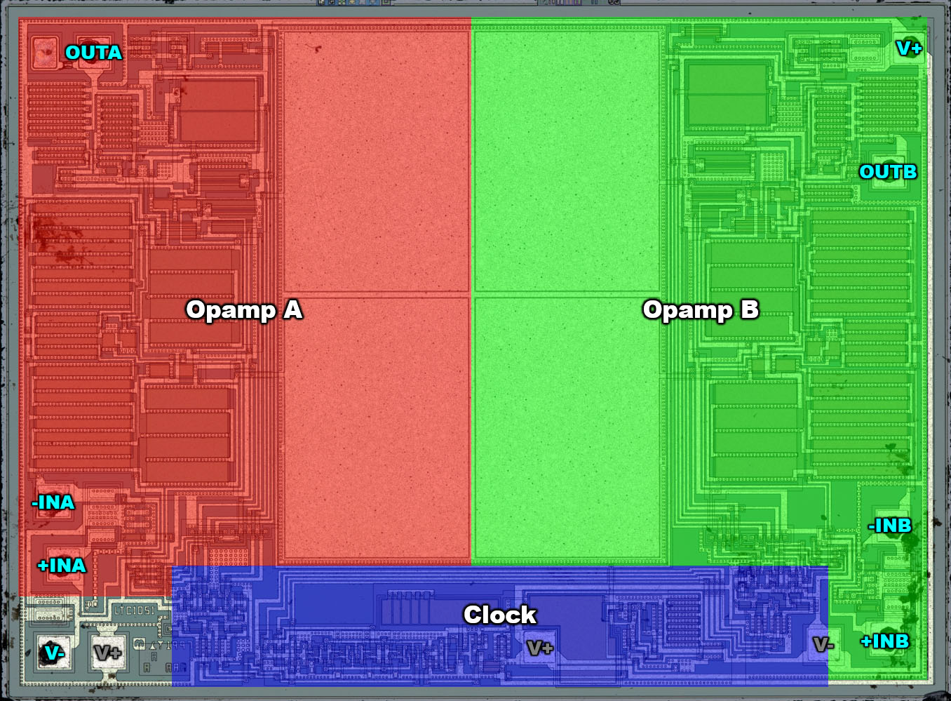
It's probably same thing as with MCP6024: two dual dice can be installed together to realize a quad. The top die gets its V+ in bottom left and V- in bottom right. The bottom die is rotated 180° so its supply connections are swapped.

I suppose it works out cheaper than designing a quad die and disabling half of it for the dual ;)

The circuit corresponds to the block diagram in the LTC1052 datasheet. The datasheet states that the amplification factors of the amplifiers gm1 and gm6 must be as equal as possible for proper function. Furthermore, these are the amplifier stages with the high amplification factors. Accordingly, these two sections are relatively large and have the same structure.
These things look like PMOS differential pairs with PMOS current sources in the center of the die and NMOS current mirrors.
Hmm, how far are you from a complete transistor level schematic of this opamp?
2
Well if the motors are to sync up and do their thing then all that I can do is have the slave motor provide the same torque as the master speed controlling motor.

So if I send a speed demand in the PDO message and then send a sync message the master will take the new speed demand and respond with a torque target. Now as it stands I don't know if that torque target will be what it was doing or what it is planning to do now that it has the go ahead for the new speed. The sync message basically trigger action on previous commands received (RX PDO) and prompts the sending of up to date information (TX PDO).

So the slave motor will then see the masters torque target as it's torque demand, but it will not act on the demand until it gets another sync message. So at best the slave will be one cycle behind the master unless I can change the settings in the slave so that it reacts immediately to the RX PDO that contains the torque demand.

If the sync message is sent at a much faster rate than the master speed controlling motor can to keep up with any load changes that affect speed then the slave motor will see new torque demands faster than the master is settling at so the action of the slave motor that must be much faster than the master will become part of the masters own control of the speed.

At the moment in dual torque control I am sending sync messages every 3ms but I make a change on every 3rd message to give the motors time to settle before I act on the data and I do that alternately so each motor only makes a change every 18ms. So with this new method that would be the equivalent of sending 6 updates between full control cycles. So I slow down the reaction of the speed controller motor and speed up the reaction of the torque control motor and now that I am doing less processing in my CAN Open master controller I can send the sync message even faster.
3
Security / Re: Microsoft repackages apps with a telemetry .NET wrapper
« Last post by Karel on Today at 07:35:15 am »
I would say that Windows is a great modular spyware system which supports some operating system functions  :D

Yes! This is probably an hyperbole though! MS is only doing this to improve your user experience. Don't you want your experience to be improved?

Yes, I want my experience to be improved. That's why I moved away from ms windows.
Not just at home, also at work (including some colleagues).
4
I have the ZB3530HL & have attempted to use the software provided for the ITECH RF-A350. The software connects ok (the ZB3530HL displays "PC Link" on the LCD). I'm using a USB-Serial lead on Windows 11. When I press "Run" with a suitable configuration, the machine does nothing & the "Now" section at the top shows nothing in the Temperature field. I've tried with flow control & as admin.

I've tried searching for an answer online to no avail. Has anyone been able to get this working successfully & what's the trick?

Pete
5
FPGA / Re: Analog video output with FPGA ?
« Last post by gf on Today at 07:31:15 am »
Should I build a PWM or PDM DAC inside the FPGA ? (in PAL, with 52us per line, 320 columns, 256 possible values and 4 PWM cycles per pixel, that would mean  6gHz clock... probably cheaper to save on the FPGA and use a DAC, but maybe PDM would be doable ?)

Delta-sigma modulation does not need such a high oversampling ratio. A 2nd order modulator with 2-level (binary) output has a theoretical SQNR of ~65dB with 32x oversamling, or ~80dB with 64x oversampling. For 5 MHz bandwidth, this would be 320 MSa/s (32x) or 640 MSa/s (64x). Maybe a little more if you want some headroom, but not 6GSa/s.

See also https://classes.engr.oregonstate.edu/eecs/spring2021/ece627/Lecture%20Notes/2nd%20&%20Higher-Order2.pdf

Edit: How much SNR do you need for analog video? I guess hardly more than 50dB. So even 16x oversampling may suffice, but that's already borderline.

Btw, does the TV have RGB inputs, or do you need a composite video signal?
6
Metrology / Re: Yet Another Hammon Divider (YAHD)
« Last post by thermistor-guy on Today at 07:25:17 am »
.... Also, be sure to use hemostats or some kind of heatsink when you solder them, lest they change value by more than you might think!

Good idea in principle. Another point: after soldering, give the resistor network a day or two to settle (unpowered).

I've had a situation where some cheap metal film resistor networks I made were way out of tolerance soon after soldering,
but measured almost exactly right the next day. I thought I'd ruined the networks, by soldering them without a heatsink,
but no - they turned out fine.
7
Test Equipment / Re: New Hantek DSO2X1X models?
« Last post by OLderDan on Today at 07:19:27 am »
I have just learned what the ref save and recall does and was wondering if there was any way to reposition the image or do I continue to setup the trace in the position I want the reference image to be displayed.
I wish there was a more complete help system for this oscilloscope, some of the inbuilt pages are empty and the only way I even understood what save and recall a ref even did was an out of context comment on a you tube video I was watching!
I finally understand the connection to time in ms ns and the actual frequency in Hz thanks to experimenting with my dso2d15, and even more useful, how to convert between SI units while measuring a capacitors charge rise to determine its value, I discovered the use of zooming the screen when looking at a long uart packet, and using the two probe tips and math function to make differential readings.

Maybe there is room in this thread for a RTFM tips section?
8
Test Equipment / Re: Choosing between entry-level 12-bit DSOs
« Last post by shapirus on Today at 07:13:55 am »
I didn't get any wobble within normal range, and then I still don't get anything as crazy as what you showed in your screenshot. It mostly shrinks and the counter gets farther and farther off. Near the end before it resets, it looks a little wonkier.
Yeah looks very reasonable. I think there's no doubt now that the signal processing algorithms are implemented much better in this scope than in the Rigol's DHO800/900.

Now, let's see if someone will be willing to repeat a similar test with the Siglent's SDS800X HD series :).
9
Projects, Designs, and Technical Stuff / Re: Homebrew Lock-In Amplifier
« Last post by RoGeorge on Today at 07:10:29 am »
In case you don't have the time to build a dedicated LIA, this oscilloscope trick might be a good-enough replacement:
https://www.eevblog.com/forum/projects/oscilloscope-with-trace-averaging-as-a-lock-in-amplifier-(rigol-ds1054z)/
10
What's wrong with the tl494?

The output is slow archaic junk.

I have heard other people say fairly often that there are much better PWM IC out there, but nobody seems to be able to point to one with access to both inverting and non inverting pins of the error amplifiers.
I have spent many hours on digikey looking, but havent had much luck.

Voltage feed-forward would be nice

and pulse skipping too

The Tl598 seems to be the tl494 with a better output section.
And states "Internal Circuitry Prohibits Double Pulse at Either Output"
Pages: [1] 2 3 4 5 6 ... 10 Next