I also suspect to know the true differences we'll need to remove the covers from the front ends(something Dave didn't do).
Do you have a 1GHz scope or SA to check PLL output clock (should be in 500-1000Mhz range)?
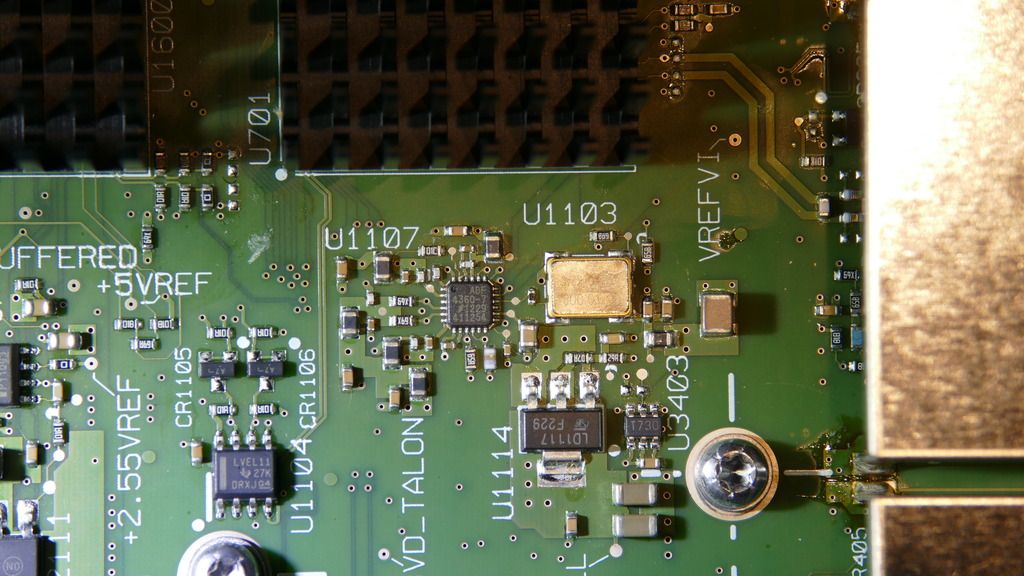
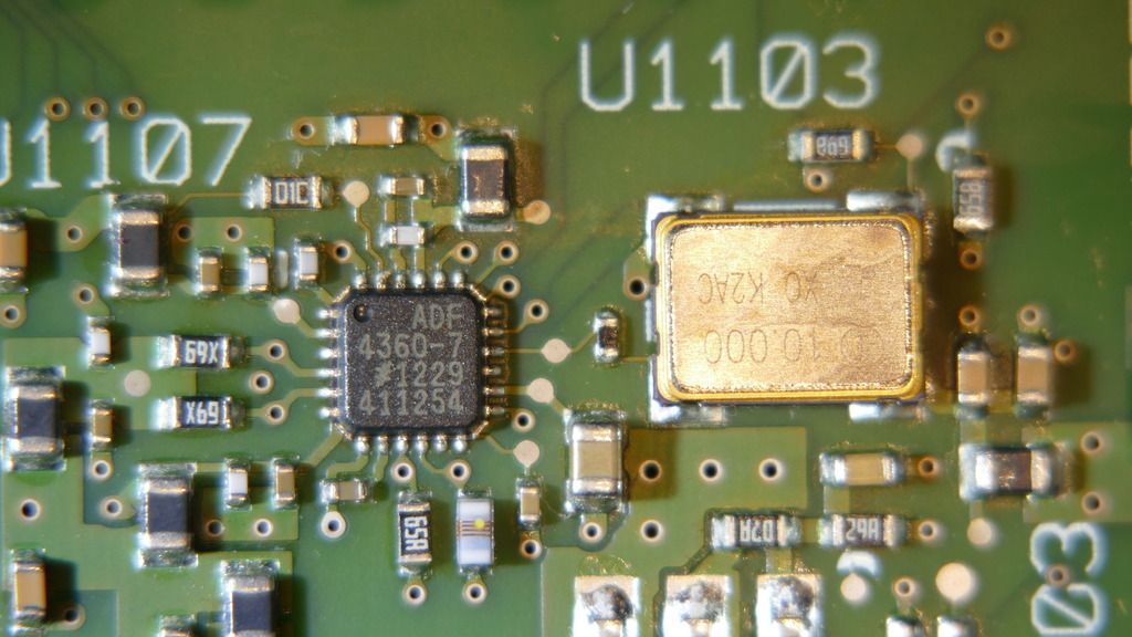
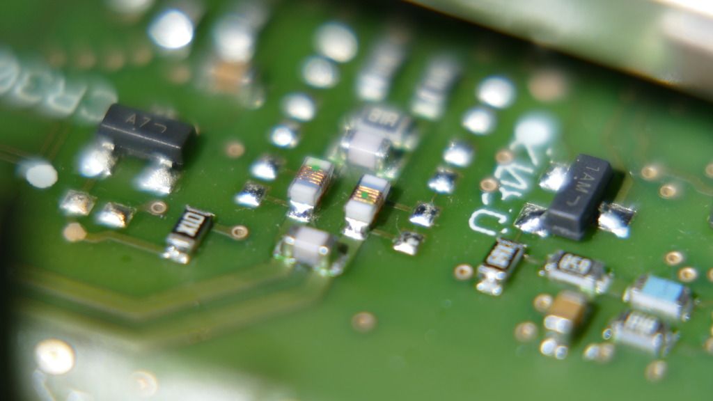
PLL is on the top layer, just between two ADC chips. No need to remove the main board.
See the photo (circled). Both single-ended or differential probe will catch the frequency.
That could be acq. clock (1GHz) or memory clock (667MHz) PLL.
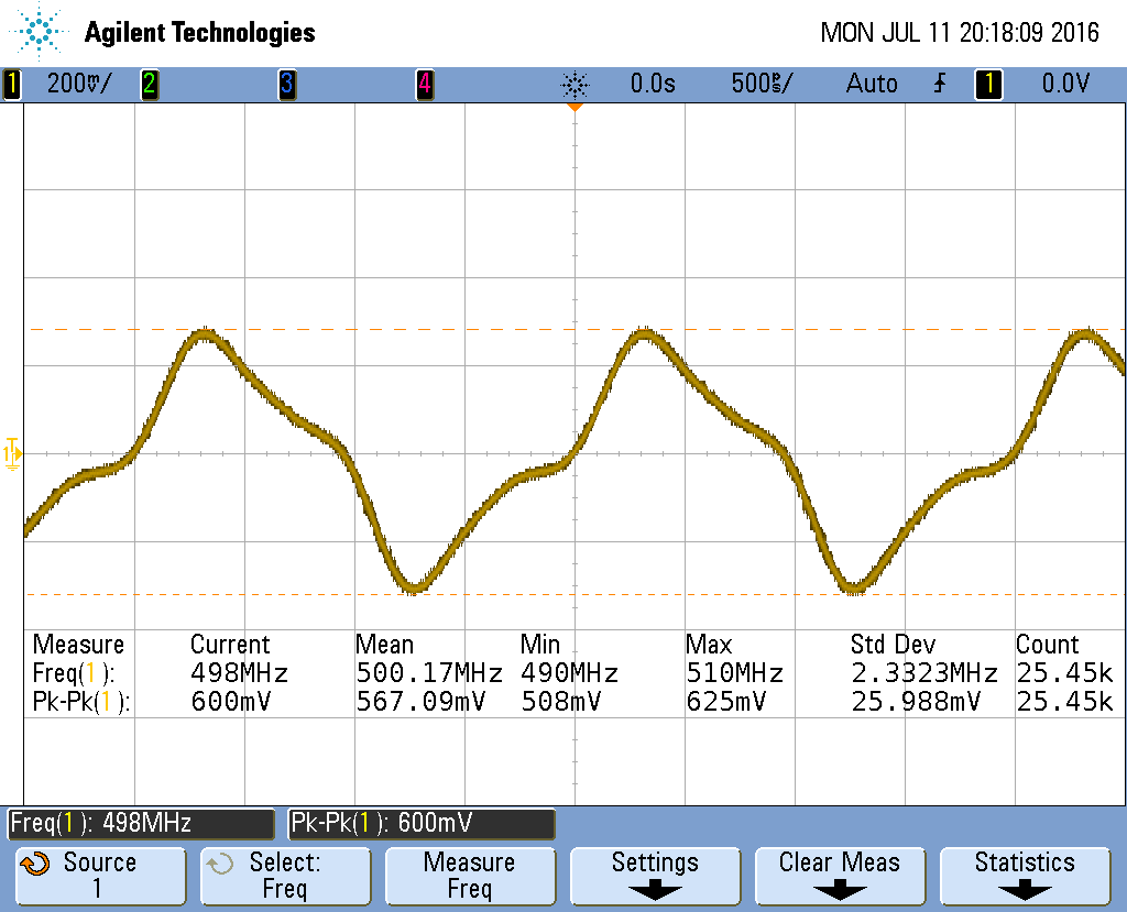
If it's of any help, that PLL in an MSO X3104A is operating at 625MHz, as detailed here:
https://www.eevblog.com/forum/blog/eevblog-683-rigol-ds1000z-ds2000-oscilloscope-jitter-problems/msg587159/#msg587159
Keysight firmly maintains the front ends are not all the same. For the 3000X series there is a 70/100/200 MHz version, a 350/500 MHz version and a 1 GHz version(with the higher sampling rate).
Can confirm that this is definitely the case. There's a hardware difference.
I'd also say that we're generally pretty conservative with our bandwidth ratings, so I'm interested to see what bandwidth you guys can coax out of the 70-200 MHz board.
I'd also say that we're generally pretty conservative with our bandwidth ratings, so I'm interested to see what bandwidth you guys can coax out of the 70-200 MHz board.
Hello Daniel! Thank you for not being angry at us for all these hardware modifications.
Default 70-200MHz board gives out roughly 240MHz at -3dB level.
I think the board could be pushed to 500MHz level by component replacement but final re-calibration may become be a very serious issue.
If it's of any help, that PLL in an MSO X3104A is operating at 625MHz, as detailed here:
5GSa/s done!Great help MarkL!
I've successfully pushed my board to 5GSa by inductor replacement. I've used 9.1nH Murata LQW18A for a center frequency of 639MHz. Coilcraft 0603CS-10NXGE or Murata's 2% LQW18A 10nH 2% must be the best choice.
Original inductors must be Coilcraft 0603CS-15NX or 0603CS-12NX. 15nH makes more sense for 500MHz output, but I'm sure I see some yellow (not green) dot on them.
Works w/o issues at 5GSa and different donwnsample rates. Time measurements are perfect.
I'm now on chimera with 5GSa/s sample rate and 350MHz software bandwidth. Extra sample rate makes no real sense for this BW, but it's a step forward.
If it's of any help, that PLL in an MSO X3104A is operating at 625MHz, as detailed here:
https://www.eevblog.com/forum/blog/eevblog-683-rigol-ds1000z-ds2000-oscilloscope-jitter-problems/msg587159/#msg587159
Thanks! Extremely useful. PLL inductor should be in 9-10nH range I suppose?
4GSa models should use 500 MHz then (1/8 of sampling rate). Needs to be confirmed too.
BTW, how did you manage to get register values? SPI bus tap? Any chance you've got some photos of 3104A's main board?
Sorry, I didn't measure the inductors while I was in there, but I did take some photos. They're not the greatest quality in terms of lighting. I've put them here for you (18MB is way beyond the eevblog posting limit):
http://www.employees.org/~markl/msox3104a_pics.zipSpace on that server is fairly limited, so don't expect the file to stick around for more than a week or two.
I captured the SPI bus with either a Saleae Logic 8 or Logic Pro 16; I can't remember which one I pulled out of the drawer.
Great - you figured it out as I was typing this!
Space on that server is fairly limited, so don't expect the file to stick around for more than a week or two.
Thanks again MarkL! Fetched that.

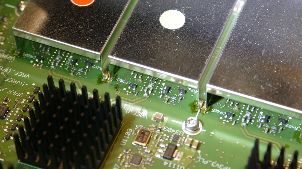
MarkL's photos indicate a sure difference in frontend zone's PCB topology for 1GHz version.
Too bad there are no photos without the shields.
Good news: 500MHz board is the same (but components are not). Hope input ASIC is the same too.
Amazing progress in a short amount of time. Fingers crossed a 200 to 500 MHz upgrade is possible without extreme part changes.
btw, I do have a spectrum analyzer good to 6 GHz and signal gen to 8 GHz for testing. I have no probe for the spectrum analyzer but am sure a small loop would still pickup the PLL frequency.
btw, I do have a spectrum analyzer good to 6 GHz and signal gen to 8 GHz for testing. I have no probe for the spectrum analyzer but am sure a small loop would still pickup the PLL frequency.
PLL part is done thanks to MarkL who reported the exact frequency.
Here is my current chimera (I'll be shy on the serial number for Keysight not to ban my unit for unauthorized mods). Unit is fed with 100Mhz 0 dBm. Note the sampling rate

FWIW these are the pics of the 3054a. If you open them in photobucket (yes, I know  ) then you can get higher definition.
Awesome! Thank you very much for the clock and amazing photos!
Better snap here of the anti aliasing filter, photobucket seems to have dropped the resolution significantly even if you download it rather than use the embedded version. Orginal pics were at 20M pixels.

Better snap here of the anti aliasing filter, photobucket seems to have dropped the resolution significantly even if you download it rather than use the embedded version. Orginal pics were at 20M pixels.
All I download is 1024 x something, even marked by photobucket as "original".
Last pic is the best btw.
Unshielded 200MHz board frontend pictured.
Note the output coils difference on 3054A and this 3014A: 5 wire turns vs. 9 turns. Different cutoff frequency guaranteed.
Here is a part of MarkL's photo with the best view to 1GHz front stage.
Looks like a "side ways" of AA filter are partially mounted here.
Would be nice to get any better photos
I have the 1 GHz version MSO-X 3104A and can take some pictures tomorrow.
May be that helps you.
Here is a part of MarkL's photo with the best view to 1GHz front stage.
Looks like a "side ways" of AA filter are partially mounted here.
Would be nice to get any better photos
Hint taken, and I'm willing to take photos of any area you'd like in more detail if you want to describe it. But if it means unsoldering the front end shield, I'm afraid I'm not up for that. The scope is in daily use for business and has a service contract. I don't want to mess with it that much.
Perhaps HighVoltage is braver than I.
I have the 1 GHz version MSO-X 3104A and can take some pictures tomorrow.
Hint taken, and I'm willing to take photos of any area you'd like in more detail if you want to describe it. But if it means unsoldering the front end shield, I'm afraid I'm not up for that.
Thanks for your will to help!
Where are still much interesting with the shields intact:
- AA filter in fine details via the top side window (like Howardlong's);
- relays photo from the smaller bottom windows;
- photo of the board's bottom side (need to remove the main board);
- you can also try to read ASIC marking via the top window.
I'm pretty sure 3000 series 200-500MHz boards are trimmed of 1GHz 50 Ohm signal path routing. Like K201 unpopulated relay switching signal to the dead end.
This Dave's photo from 4000 series could be useful as a reference:
https://www.flickr.com/photos/eevblog/8181526726/in/album-72157631997535516/That's 200MHz board of 1.5GHz capable series. I think the alternative way for 50 Ohm coupling goes through K201 and further to that big 6 pin through-hole component. K203 may be left unpopulated on 1GHz board.
Works w/o issues at 5GSa and different donwnsample rates. Time measurements are perfect.
I'm now on chimera with 5GSa/s sample rate and 350MHz software bandwidth. Extra sample rate makes no real sense for this BW, but it's a step forward.
Did you measure how hot it gets now? Be careful not to burn up your scope.
Did you measure how hot it gets now? Be careful not to burn up your scope.
Nope. 5GSa version use the same heatsinks so I don't bother atm.
I've tried to relax output AA filter, but Agilent wins this round. No bandwidth improvement at all. Should be another filter in input path or software-enforced limit.
Maybe some new photos from 3054A or 3104A would show what to do next.
Unshielded input photo seem to be needed too

How do they do the 20 MHz bw limit? And is the upper end limited in a similar way.
How do they do the 20 MHz bw limit? And is the upper end limited in a similar way.
It's 200MHz upper limit, exactly as declared for this board. No low end limit here.
Is it possible to dump all internal files to USB drive on 2.41 without the LAN module? I'd like to examine the filesystem, but some time is required to make a DIY LAN.
You can switch in a 20 MHz bandwidth limiter though on all versions - is that handled by discrete hardware in the front end, the Agilent branded chip or possibly even in megazoom asic?
And if you buy a 100 MHz scope is the front end still running at the 200 MHz bandwidth or is it limited? I can check that tonight on my scope if needed. If they don't limit it then the only difference would be a timebase setting which seems silly.
You can easily unpack the firmware to take a look at the files on your PC. It is the same steps needed to make a bootable usb drive etc, the info is all in this thread a number of pages back.