-
You don't even now what is KVL!
KVL is a special case of Faraday's law when you don't have a time-varying magnetic field in the surface enclosed by the path of the circuit.
Your ignorance is laughable!
-
Your ignorance is laughable!
You'll stop laughing when you finally understand electromagnetism. -
And, Jesse, when I say "listen to the guys in a garage" I am not comparing them to me, but to the university professors who wrote books and papers where this problem was carefully analyzed.
Purcell, Morin, Roche, Ramo, Whinnery, VanDuzer, Romer, Rosser, Zahn, Haus, Melcher, Nicholson, Brandao Faria, ...
Ahhhh, and when I read your articulate posts so artfully penned from your garage, I would be comparing them then to Maxwell, Feynman, Belcher, McDonald, etc., ..., .
See how useless that is? -
have you noticed that Jesse is repeatedly posting the same image of a circuit with a transformer, two outputs on a circuit with resistors and a lot of voltmeters? Suppose one turn around the core gives you an emf of 1V.
Can you place the values of your "path independent voltage" inside all those voltmeters?
What does that even mean? We're talking about KVL here. You use self contained lumped two-terminal elements here. You are trying to put KVL on trial for what goes on inside of a black-box lumped element.
And according to Team Lewin's fully endorsed top of the line textbook, transformer windings are completely acceptable:Quote from: Desoer-Kuh
Lumped circuits are obtained by connecting lumped elements. Typical
lumped elements are resistors, capacitors, inductors, and transformers.
We have encountered them in the laboratory, and we can see them in our
radio sets. The key property associated with lumped elements is their
small size (compared to the wavelength corresponding to their normal
frequency of operation.) From the more general electromagnetic field point
of view, lumped elements are point singularities; that is, they have negligible
physical dimensions. In this way they are similar to a particle.
Lumped elements may have two terminals, as in a resistor, or more than
two terminals, as in a transformer or transistor. For two-terminal
lumped elements, it can be shown that the general laws governing the
electromagnetic field, together with the restriction on physical size indicated
above, imply that at all times the current entering one terminal is
equal to the current leaving the other terminal, and that the voltage difference
between the two terminals can be unambiguously defined by physical
measurements. Thus, for two-terminal lumped elements, the current
through the element and the voltage across it are well-defined quantities. For
lumped elements with more than two terminals, the current entering any
terminal and the voltage across any pair of terminals are well defined at all times.
For the remainder of this book, any interconnection of the lumped
elements such that the dimensions of the circuit are small compared with the
wavelength associated with the highest frequency of interest will be called
a lumped circuit.
As long as this restriction on the size of the circuit holds, Kirchhoff's
current and voltage laws (to be discussed in Secs. 3 and 4) are valid. This
restriction is a consequence of the fact that Kirchhoff's laws are approximations
of Maxwell's celebrated equations, which are the general laws
of the electromagnetic field. The approximation is analogous to the fact
that Newton's laws of classical mechanics are approximations to the laws
of relativistic mechanics. Even though they are approximations, the laws
of Newton and Kirchhoff can be applied to a large number of practical
(Glowies Mine HEHE)
Team Lewin provided this very citation and assured me that this was the Bently or Rolls Royce or whatever of textbooks.
It is utterly clear that as long as the restrictions it describes are conformed to, transformer and inductor windings are perfectly valid as elements in a loop for KVL.Quote(Pretty sure Jesse doesn't know either, because I've asked and he refused to answer)
If I refused to answer any of your questions it was for one of two reasons: 1: It was incoherent or unambiguous words which did not actually form an unambiguous question.
Or 2: At some point I realized you were just throwing muddy questions at the wall in hopes one would stick while refusing to answer a single one of mine so I began question bargaining which meant I had to refuse to answer questions just to get you to answer a couple of mine. Doesn't mean I didn't know the answers though.
And you still have not answered MY question as I asked it. Sure you asked yourself your own question and answered it, but you have not answered MY question as I asked it:
Question: In the following diagram, in a real life physical lab test performed with real (time synchronized) volt meters with a real transformer and real resistors CONNECTED AS SHOWN, will the readings of all the volt meters sum to zero, within the accuracy and resolution limitations of the volt meters? YES or NO.
(Or if you believe SOMETIMES is the answer, then answer SOMETIMES and explain one scenario for a YES condition and one scenario for a NO condition WITH THE VOLT METERS AND ALL COMPONENTS CONNECTED AS SHOWN - Running additional conductors through the transformer core is not allowed - nor is removing existing conductors from through the transformer core!)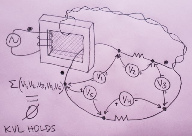
-
If the induced EMF is not in the path of the circuit, yes, you can include it in KVL. If not, KVL fails.
So where does that leave the venerable transformer secondary? Is the voltage across the terminals of a transformer secondary considered "Induced EMF which is in the path of the circuit?"
I think what you mean to say is that IF there is UNDOCUMENTED EMF across any part of the loop, then KVL fails.
That undocumented voltage could be from the photovoltaic effect, the electrochemical effect, the seebeck effect, or yes, even magnetically induced voltage, and KVL will fail.
But if all element voltages are accurately measured then KVL holds.
The only real question we must answer is whether "the voltage difference
between the two terminals can be unambiguously defined by physical
measurements." (Desoer-Kuh)
If the answer is yes then the answer is yes, KVL holds.
And the fact is that for closed-magnetic-circuit-core transformers, the output voltage of a secondary winding (heh as well as the input voltage of the primary) can almost always be unambiguously physically measured.
And in many open-magnetic-circuit type core transformers the voltage difference can also be unambiguously physically measured, and so KVL holds there too.
I honestly cannot understand why Team Lewin won't admit to even the undeniable and move on to the finer points.
Question: In the following diagram, in a real life physical lab test performed with real (time synchronized) volt meters with a real transformer and real resistors CONNECTED AS SHOWN, will the readings of all the volt meters sum to zero, within the accuracy and resolution limitations of the volt meters? YES or NO.
(Or if you believe SOMETIMES is the answer, then answer SOMETIMES and explain one scenario for a YES condition and one scenario for a NO condition WITH THE VOLT METERS AND ALL COMPONENTS CONNECTED AS SHOWN - Running additional conductors through the transformer core is not allowed - nor is removing existing conductors from through the transformer core!)
It's time you admit that the answer to the above question is YES: So long as the voltage across the terminals of the element can be unambiguously defined by physical measurement, then KVL will hold.
And besides, actual lab results match KVL. It's obviously holding!
-
Quote
Let the components of the electromotive intensity be X, Y, Z.
The electromotive intensity at any point is the resultant force on a unit of positive electricity placed at that point. It may arise (1) from electrostatic action, in which case if V is the potential,
\$X=-\frac{dV}{dx},Y=-\frac{dV}{dy},Z=-\frac{dV}{dz}; (1)\$
or (2) from electromagnetic induction, the laws of which we shall afterwards examine; or (3) from thermoelectric or electrochemical action at the point itself, tending to produce a current in a given direction.
We shall in general suppose that X, Y, Z represent the components of the actual electromotive intensity at the point, whatever be the origin of the force, but we shall occasionally examine the result of supposing it entirely due to variation of potential.
Apart from the fact that Maxwell is simply enumerating the EMF available at the time: electrochemical piles/electrostatic machines, thermopiles and em induction (remember, if you consider localized sources you can apply what today we call "extended KVL") - what if it actually contradicted Maxwell?
Maxwell believed in the existence of the luminiferous ether. He was wrong.
What we today call "Maxwell's equations" is the result of the work of Heaviside, using the notation expressed in the treatise would be maddening. Expliciting all gradients, curls, divergences...
A lot of thing has changed since 1865.
But one thing that has not changed since the time of Maxwell is that KVL explicitly includes electromagnetic induction EMFs which are not to be treated differently from any other EMFs, "whatever be the origin of the force"!
I'm pretty sure Team Lewin doesn't even know what they are arguing for, much less what they are arguing about.
Otherwise they'd be willing to concede the obvious stuff and move on to the finer details, but even that cannot happen.
It's been fascinating for sure.
But what baffles me is Team Lewin's refusal to draw a definitive line in reasoning and say "Here's where you're wrong. (Insert reason)" ("You" being Team KVL.)
The only thing they really seem certain of is that Lewin cannot be wrong. Maybe former students? Maybe fellow Dutchmen? I've read that the Dutch are both very loyal to their own as well as very tenacious in negotiations with others.
At the very least I'd have expected Team Lewin to say "Yes, the volt meters in your diagram will sum to zero, and KVL does appear to work, but due to a certain technicality of a certain definition, we say KVL isn't holding.."
But we can't even get that much from them, which means they don't even understand the topic much less what they are arguing for.
Team Lewin also seems to ignore the fact that some PhD Physics Professors also disagree with them -- it doesn't take a genius to see that not all PhD Physics Professors agree on the topic so there must be room for discussion.. But no, Lewin defines reality and we're supposed to ignore the others. -
But no, Lewin defines reality and we're supposed to ignore the others.
It is waste to argue with true believers because they simply ignore anything that does not support their beliefs. -
I think what you mean to say is that IF there is UNDOCUMENTED EMF across any part of the loop, then KVL fails.
What if it is written off, instead of undocumented? I don't know, by some very basic electrostatic phenomenon that you're ignoring along the path you chose?I'm pretty sure Team Lewin doesn't even know what they are arguing for, much less what they are arguing about.
You're ignorant about the electromagnetic phenomenon. But that's not a problem. The problem is that you don't even know it.
This is what I call recursive ignorance. It is the kind of ignorance that is so deep that it doesn't allow you to realize that it exists.QuoteBut what baffles me is Team Lewin's refusal to draw a definitive line in reasoning and say "Here's where you're wrong. (Insert reason)" ("You" being Team KVL.)
This whole thread is a monument erected to your ignorance of electromagnetism. So, just read the thread and you'll instantly get where you're wrong.QuoteThe only thing they really seem certain of is that Lewin cannot be wrong. Maybe former students? Maybe fellow Dutchmen? I've read that the Dutch are both very loyal to their own as well as very tenacious in negotiations with others.
Lewin is not wrong because we independently learned the theory (I did decades ago) and repeated the experiments, and the results predicted by the theory are precisely the same.QuoteTeam Lewin also seems to ignore the fact that some PhD Physics Professors also disagree with them -- it doesn't take a genius to see that not all PhD Physics Professors agree on the topic so there must be room for discussion..
But none of them said Lewin is wrong. And yes, KVLers proved to be no geniuses up to now.QuoteBut no, Lewin defines reality and we're supposed to ignore the others.
What defines reality is Nature. Lewin just happened to be the harbinger of it to you. Learn to live with that.It is waste to argue with true believers because they simply ignore anything that does not support their beliefs.
We're engineers. We don't believe. We learn engineering and test things in the lab, and what we say is the result of that. -
have you noticed that Jesse is repeatedly posting the same image of a circuit with a transformer, two outputs on a circuit with resistors and a lot of voltmeters? Suppose one turn around the core gives you an emf of 1V.
Can you place the values of your "path independent voltage" inside all those voltmeters?
What does that even mean?
It means that you cannot even put numbers of your 'McDonald voltage' in those voltmeters without a numerical simulation. That's the problem of using the scalar potential difference as definition of voltage. And if you choose to use minus the path integral of Etot.dl, then you will have to face that there are configurations of voltmeters where KVL dies.
On the other hand, I have zero problems in putting values into those voltmeters that will be what you will read in the real world. And I have zero problems in admitting that for some configurations KVL will die.QuoteAnd according to Team Lewin's fully endorsed top of the line textbook, transformer windings are completely acceptable:
Quote from: Desoer-Kuh
Lumped circuits are obtained by connecting lumped elements.
It just shows you do not understand what you read. Go back a few pages to my posts about "lumpED lumpABLE and UNlumpable" circuits, I cannot repeat everything every time you reset to default (like you do on your channel, when you keep mentioning that sentence by Belcher which I have extensively shown it was not referred to Lewin's ring).QuoteQuote(Pretty sure Jesse doesn't know either, because I've asked and he refused to answer)
If I refused to answer any of your questions it was for one of two reasons: 1: It was incoherent or unambiguous words which did not actually form an unambiguous question.
Or 2: At some point I realized you were just throwing muddy questions at the wall in hopes one would stick while refusing to answer a single one of mine so I began question bargaining which meant I had to refuse to answer questions just to get you to answer a couple of mine. Doesn't mean I didn't know the answers though.
and
3. you don't know how to answer.
I see that you have banned another user on your YT channel.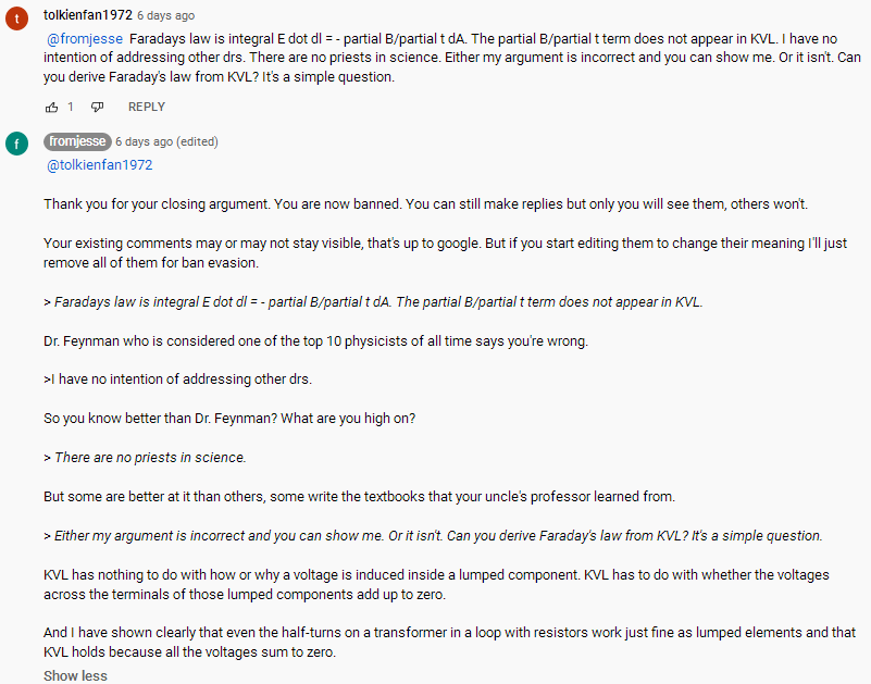
https://i.postimg.cc/KjvfpC5f/screenshot.png
I wonder why you do that. Quote
And you still have not answered MY question as I asked it.
I did answer your question. And I showed you that even if you can find configurations where KVL works, certain circuits also admits configurations where KVL does not work. And I showed you, by using the unlumpable Lewin ring, that even in such a case you can devise a configuration of elements and voltmeters where KVL holds. So, your example does not mean anything.
Here, let me try to explain with an analogy:
In the presence of water there are situations where you cannot walk.
Of course, if you are on the shore, or on a pier, or on a boat, you can walk even if you are close to water.
The problem is that this is not always true because when you are not on the shore, not on a pier, not on a boat, but you are in the middle of the ocean, you cannot walk.
Your voltmeters configuration is like a boat in the middle of the ocean. You keep insisting "see, I'm in the presence of water the middle of the ocean and I can walk, therefore we can walk on water even when we are in the middle of the ocean".
No, you can't.
But you do not understand that, and keep proposing that circuit as if it could represent some difficulty...QuoteQuestion: In the following diagram, in a real life physical lab test performed with real (time synchronized) volt meters with a real transformer and real resistors CONNECTED AS SHOWN, will the readings of all the volt meters sum to zero, within the accuracy and resolution limitations of the volt meters? YES or NO.
(Or if you believe SOMETIMES is the answer, then answer SOMETIMES and explain one scenario for a YES condition and one scenario for a NO condition WITH THE VOLT METERS AND ALL COMPONENTS CONNECTED AS SHOWN - Running additional conductors through the transformer core is not allowed - nor is removing existing conductors from through the transformer core!)
You are showing a boat in the middle of the ocean. Yes you can walk on the bridge of that boat.
But you still cannot walk on water.
Is it clear now?
(It is a rhetorical question)
Now, would you care to put values in those voltmeters in that 'oh, so tricky' circuit of yours?
Edit: grammar -
But what baffles me is Team Lewin's refusal to draw a definitive line in reasoning and say "Here's where you're wrong. (Insert reason)" ("You" being Team KVL.)
The only thing they really seem certain of is that Lewin cannot be wrong. Maybe former students? Maybe fellow Dutchmen? I've read that the Dutch are both very loyal to their own as well as very tenacious in negotiations with others.
At the very least I'd have expected Team Lewin to say "Yes, the volt meters in your diagram will sum to zero, and KVL does appear to work, but due to a certain technicality of a certain definition, we say KVL isn't holding.."
But we can't even get that much from them, which means they don't even understand the topic much less what they are arguing for.
Team Lewin also seems to ignore the fact that some PhD Physics Professors also disagree with them -- it doesn't take a genius to see that not all PhD Physics Professors agree on the topic so there must be room for discussion.. But no, Lewin defines reality and we're supposed to ignore the others.
Lewin is just one of many, many, many other professors who know how to correctly apply classical electrodynamics. What we (well, I at least) call the Romer-Lewin ring is mentioned in a 1969 teaser by Moorcroft, followed by a discussion published the year after
D. R. Moorcroft
Faraday's Law, potential and voltage: discussion of a teaser
received July 1969, published on American Journal of Physics 38, 376 - March 1970
doi 10.1119/1.1976329
there, Moorcroft proposed a distinction between the definitions of potential difference (the scalar potential difference) and voltage (minus the path integral of the total electric field Etot.dl).
What voltmeters measure and an application to "the ring" is also discussed in Romer's paper - with the same conclusions Lewin arrive at.
Robert H. Romer
What do voltmeters measure? Faraday's law in multiply connected regions
American Journal of Physics vol 50, no 12, December 1982
The ring, the electric field configuration, its charge distribution and even the Poynting vector field is discussed in a paper by Mark Heald
Mark A. Heald
Energy Flow in Circuits with Faraday EMF
American Journal of Physics, 56 (6), June 1988
same exact conclusion as Lewin's
The same can be said about the paper by Roche
J. Roche
Explaining electromagnetic induction: a critical re-examination.
The clinical value of history in physics.
Physics Education, Volume 22, Number 2
What a voltmeter measures in the case of a loop with a single resistor is treated in
Howard W. Nicholson
What does the voltmeter read?
Am. J. Phys. 73 (12), December 2005
And then there are books, lots of books from many authors (Purcell, Haus and Melcher, Ramo Whinnery VanDuzer, Brandao Faria, ...)
And videos, like the videos from MIT or those from Micheal Melloch of Purdue University.
Electric and Magnetic Fields
Prof. Micheal R. Melloch
School of ECE - Purdue University
videos of the same author that you yourself linked in your channel, evidently without understanding they were on the same position as Lewin's.
I think I understand where this fixation for Lewin comes from: he expressed the limitations of KVL in terms that even people who have no idea what a path integral is can understand. They understood the sentence "KVL is for the bird" and nothing of what is behind and now Lewin is their boogey man.
They do not even understand what Belcher and McDonald say, they only get a few sentences here and there. Like you with that sentence by Belcher that is about the RLC lumped circuit. Or with what McDonald proposes, ie using the scalar potential difference as definition of voltage - for which you do not understand the implications (what would be the McDonald voltage in the McDonald voltmeters of your circuit? You cannot even answer that).
Belcher, McDonald and Notaros require both fields or both potentials to correctly describe Lewin's ring. KVLers ignore this simple fact and think the coulombian field alone (sometimes the induced field alone) or the scalar potential alone suffice.
Ignorance is bliss, they say.
-
Lewin is just one of many, many, many other professors who know how to correctly apply classical electrodynamics. What we (well, I at least) call the Romer-Lewin ring is mentioned in a 1969 teaser by Moorcroft, followed by a discussion published the year after
Sredni (the king of cherry picking!), have you calculated the voltage between nodes A and D, VAD yet? Have you figured what is the difference between the voltage between two nodes and the voltage measured by a 'voltmeter'?
Lewin, and team Lewin by that matter, are so wrong that they even disagree with what Maxwell explicitly says. Let start with definition of KVL as stated by Maxwell in "A Treatise on Electricity & Magnetism" from 1873:
[Page 406 article 282b]
The theory of conjugate conductors has been investigated by Kirchhoff, who has stated the conditions of a linear system in the following manner, in which the consideration of the potential is avoided.
(1) (Condition of 'continuity.') At any point of the system the sum of all the currents which flow towards that point is zero.
(2) In any complete circuit formed by the conductors the sum of the electromotive forces taken round the circuit is equal to the sum of the products of the current in each conductor multiplied by the resistance of that conductor.
Point (1) above is clearly KCL and point (2) is clearly KVL. That is followed latter on by this about electromotive forces:
[Page 418 article 297]
Let the components of the electromotive intensity be X, Y, Z.
The electromotive intensity at any point is the resultant force on a unit of positive electricity placed at that point. It may arise (1) from electrostatic action, in which case if V is the potential,
\$X=-\frac{dV}{dx},Y=-\frac{dV}{dy},Z=-\frac{dV}{dz}; (1)\$
or (2) from electromagnetic induction, the laws of which we shall afterwards examine; or (3) from thermoelectric or electrochemical action at the point itself, tending to produce a current in a given direction.
We shall in general suppose that X, Y, Z represent the components of the actual electromotive intensity at the point, whatever be the origin of the force, but we shall occasionally examine the result of supposing it entirely due to variation of potential.
We shall in general suppose that X, Y, Z represent the components of the actual electromotive intensity at the point, whatever be the origin of the force, but we shall occasionally examine the result of supposing it entirely due the variation of potential.
Now, whom should we believe?
1) Maxwell who has been proven right over and over for more than 150 years?
2) Lewin who has been proven wrong over and over again for many years, both mathematically and experimentally?
The correct option is of course 1). Unless you are Sredni, who will manage to find a way to denigrate Maxwell because what he wrote doesn't agree with his bullshit!
-
Lewin is just one of many, many, many other professors who know how to correctly apply classical electrodynamics. What we (well, I at least) call the Romer-Lewin ring is mentioned in a 1969 teaser by Moorcroft, followed by a discussion published the year after
Sredni (the king of cherry picking!), have you calculated the voltage between nodes A and D, VAD yet? Have you figured what is the difference between the voltage between two nodes and the voltage measured by a 'voltmeter'?
Yes I did, and for several paths.
The fact that you either did not understand that, or just simply revert back to factory defaults and keep asking the same questions again and again because you don't like the answer is irrelevant.QuoteLewin, and team Lewin by that matter, are so wrong that they even disagree with what Maxwell explicitly says.
Maxwell believed in the luminiferous ether.
Do you believe in the luminiferouts ether?
(Or should I ask "do you know what the luminiferous ether is"?)QuoteLet start with definition of KVL as stated by Maxwell in "A Treatise on Electricity & Magnetism" from 1873:
[Page 406 article 282b]
The theory of conjugate conductors has been investigated by Kirchhoff, who has stated the conditions of a linear system in the following manner, in which the consideration of the potential is avoided.
(1) (Condition of 'continuity.') At any point of the system the sum of all the currents which flow towards that point is zero.
(2) In any complete circuit formed by the conductors the sum of the electromotive forces taken round the circuit
I am not a native English speaker. Could you please enlighten me about what "taken round the circuit" means in English?
-
Yes I did, and for several paths.
The fact that you either did not understand that, or just simply revert back to factory defaults and keep asking the same questions again and again because you don't like the answer is irrelevant.
When you calculate the voltage VAD, there is only one path, the path of the ring circuit, which is neither changing nor moving! The other paths you mention do not exist!Maxwell believed in the luminiferous ether.
Do you believe in the luminiferouts ether?
(Or should I ask "do you know what the luminiferous ether is"?)
And here you are! Denigrating Maxwell as predicted. Also, I am pretty sure Maxwell contemplated the possibility of a "luminiferous ether", but he was not sold on it unless solid evidence of it was provided. (I think I read that somewhere in one of his writings...)I am not a native English speaker. Could you please enlighten me about what "taken round the circuit" means in English?
You need to imagine as if Sean Connery is reading the writings of Maxwell! It may make more sense to you then!
-
Yes I did, and for several paths.
The fact that you either did not understand that, or just simply revert back to factory defaults and keep asking the same questions again and again because you don't like the answer is irrelevant.
When you calculate the voltage VAD, there is only one path, the path of the ring circuit, which is neither changing nor moving!
Of course you mean the path on the right (A ---> R1 ---> D)?
Or the one on the left (A ---> R2 ---> D)?
Or the one along an imaginary line that splits the circular circuit in half? And if the circuit is not symmetric?
Now paths do not exists because the circuit is stationary
Every day something new.QuoteMaxwell believed in the luminiferous ether.
Do you believe in the luminiferouts ether?
(Or should I ask "do you know what the luminiferous ether is"?)
And here you are! Denigrating Maxwell as predicted.
Not denigrating. Just stating a fact.
Newton believed time and space were absolutes. Is this denigrating Newton?QuoteAlso, I am pretty sure Maxwell contemplated the possibility of a "luminiferous ether", but he was not sold on it unless solid evidence of it was provided. (I think I read that somewhere in one of his writings...)
https://en.wikipedia.org/wiki/Luminiferous_aether
"Albeit compatible with Maxwell's equations, electromagnetic induction of electric fields could not be demonstrated in vacuum, because all methods of detecting electric fields required electrically charged matter.
In addition, Maxwell's equations required that all electromagnetic waves in vacuum propagate at a fixed speed, c. As this can only occur in one reference frame in Newtonian physics (see Galilean relativity), the aether was hypothesized as the absolute and unique frame of reference in which Maxwell's equations hold. That is, the aether must be "still" universally, otherwise c would vary along with any variations that might occur in its supportive medium. Maxwell himself proposed several mechanical models of aether based on wheels and gears, and George Francis FitzGerald even constructed a working model of one of them."QuoteI am not a native English speaker. Could you please enlighten me about what "taken round the circuit" means in English?
You need to imagine as if Sean Connery is reading the writings of Maxwell! It may make more sense to you then!
Yeah, like Jesse, you can't answer and just try to deflect. -
Yes I did, and for several paths.
The fact that you either did not understand that, or just simply revert back to factory defaults and keep asking the same questions again and again because you don't like the answer is irrelevant.
When you calculate the voltage VAD, there is only one path, the path of the ring circuit, which is neither changing nor moving!
Of course you mean the path on the right (A ---> R1 ---> D)?
Or the one on the left (A ---> R2 ---> D)?
Or the one along an imaginary line that splits the circular circuit in half? And if the circuit is not symmetric?
Now paths do not exists because the circuit is stationary
Every day something new.
Here, from Engineering Electromagnetics by Hayt , 7th edition, page 308:
"We need to define emf as used in (1) or (2). The emf is obviously a scalar, and (perhaps no so obviously) a dimensional check shows that it is measured in volts. We define the emf as:
\$emf=\oint_{}^{}E \cdot dL\$
and note that is is the voltage about a specific closed path."
See that little circle "round" the integral, the one you often omit from your long posts? That is the path we are talking about, the path of the wires and components of the circuit.Maxwell believed in the luminiferous ether.
Do you believe in the luminiferouts ether?
(Or should I ask "do you know what the luminiferous ether is"?)
And here you are! Denigrating Maxwell as predicted.
Not denigrating. Just stating a fact.
Newton believed time and space were absolutes. Is this denigrating Newton?
Really? So why is relevant to this discussion whether or not Maxwell believed in the "luminiferous ether" or not? You are guilty here of not just one, but two fallacies: denigration and deflection.I am not a native English speaker. Could you please enlighten me about what "taken round the circuit" means in English?
QuoteYou need to imagine as if Sean Connery is reading the writings of Maxwell! It may make more sense to you then!
Yeah, like Jesse, you can't answer and just try to deflect.
Sorry, I thought you were joking or something. Who would ask such a basic question? Here:
\$emf=\oint_{}^{}E \cdot dL\$
See that little circle "round" the integral? That is what Maxwell is talking about.
-
Really? So why is relevant to this discussion whether or not Maxwell believed in the "luminiferous ether" or not? You are guilty here of not just one, but two fallacies: denigration and deflection.
Not denigrating. Just stating a fact.Maxwell believed in the luminiferous ether.
And here you are! Denigrating Maxwell as predicted.
Do you believe in the luminiferouts ether?
(Or should I ask "do you know what the luminiferous ether is"?)
Newton believed time and space were absolutes. Is this denigrating Newton?
You are the one who believe Maxwell is infallible and his Treatise is gospel. I simply pointed out that the Treatise reflects the time it was written. A time where Maxwell's equations as we know them were yet to be penned. A time where people, including Maxwell, believed in the luminiferous ether. You have quoted a passage of the Treatise where Maxwell is illustrating the sources of emf as known at the time, so what? He states explicitly:
"In any complete circuit formed by the conductors the sum of the electromotive forces taken round the circuit..."
And I am wondering: if the emf is a scalar value that results from computing the path integral of that one closed loop (as that little circle implies), why is Maxwell using the plural? You said it yourself: there is only one loop [note], so there must be only one value for the integral computed along that one loop.
I tell you why he is using the plural.
Because in that sentence he was considering the lumped emfs encountered by going around the circuit. That is what KVL was about at the time (and still is now, since its generalization outside of garages is known as Faraday's law).
note I also wonder... what if the circuit has more than one loop linking dB/dt... What single one loop would you choose to compute the one and only value of Vad?
-
As Dr.Lewin ignores emf literally in half of his circuit stating that voltage on two wires A1-A2 and D1-D2 is 0V, let's remove both from circuit completely. What we have left are two resistors. Let's take 10 Ohm wire and make full turn out of it, connect tiny 100 Ohms resistor as load. What we have in result - transformer with lossy secondary and load. Voltages on both equal obviously. It would be rather stupid to measure current through 100 Ohms load, then knowing internal resistance (10 Ohms) of transformer secondary, apply ohms law to calculate voltage
 But wait... this is what Dr.Lewin effectively does in his video "Kirchhoff's Loop Rule Is For The Birds".
-
You are the one who believe Maxwell is infallible and his Treatise is gospel. I simply pointed out that the Treatise reflects the time it was written. A time where Maxwell's equations as we know them were yet to be penned. A time where people, including Maxwell, believed in the luminiferous ether. You have quoted a passage of the Treatise where Maxwell is illustrating the sources of emf as known at the time, so what? He states explicitly:
Interesting. Maxwell is fallible, but Lewin, whom struggles to solve the simplest of circuits, is infallible them!
"In any complete circuit formed by the conductors the sum of the electromotive forces taken round the circuit..."
And I am wondering: if the emf is a scalar value that results from computing the path integral of that one closed loop (as that little circle implies), why is Maxwell using the plural? You said it yourself: there is only one loop [note], so there must be only one value for the integral computed along that one loop.
I tell you why he is using the plural.
Because in that sentence he was considering the lumped emfs encountered by going around the circuit. That is what KVL was about at the time (and still is now, since its generalization outside of garages is known as Faraday's law).
So, according to your logic in Lewin's ring, the wire on the top has half the induced EMF and the wire at the bottom has half the induced EMF. So, can you now can compute the voltage VAD?
Also, according to Maxwell (and he says it explicitly) Faraday's law is NOT a generalization of KVL. "Electromagnetic induction, the laws of which we shall afterwards examine" is just one more EMF that must be added to other EMFs when using KVL, "whatever be the origin of the force".note I also wonder... what if the circuit has more than one loop linking dB/dt... What single one loop would you choose to compute the one and only value of Vad?
Then you use KVL and KCL to the complete and correct circuit to computer VAD, as Lewin should had done when he added the 'voltmeters' to left and right of the ring. In that case he went from one loop to three loops, ignored the two extra loops, disregarded the induced voltages in the wires, calculated the voltages in the resistors using KVL, drew the wrong equivalent circuit, failed to calculate the voltage VAD, and proclaimed with grandiose fanfare that KVL doesn't work. When confronted on his massive mess, the only recourse he had was to redefine KVL. To bad for him, the definition of modern KVL was explicitly stated by Maxwell all the way back in 1873 (or earlier) which includes electromagnetic induction as one of the EMFs you have to consider.
-
3. you don't know how to answer.
I see that you have banned ano]ther user on your YT channel.
https://i.postimg.cc/KjvfpC5f/screenshot.png
I wonder why you do that.
If you don't understand it, get rid of it. He doesn't have the minimum background to understand the what the guy said. But you cannot expect anything different from these people who worship their own stupidity.They do not even understand what Belcher and McDonald say, they only get a few sentences here and there.
This is called confirmation bias, one of the most widely committed cognitive biases. They only get snippets of text, out of context, that, on the surface, seem to, but don't, support their beliefs and values. Confirmation bias is also present in the interpretation of results. Only the results that seem to confirm their bias are selected out of context; the rest, which debunk their claims, is ignored. You find this tendency in politics, religion, ideologies, but it is mortal in engineering and science.
Maxwell's equations as we know them today are the result of almost one century of research and development by brilliant scientists, including the already mentioned Faraday, Kirchhoff and Maxwell, but also countless others, like Örsted, Gauss, Ampère, Hertz, Lorentz, Heaviside, Kelvin and Einstein, for example.
It takes several years of painstaking study to master a minimal understanding of it.
You can clearly see that they do not have the appropriate background to sustain an argument. The idea of a non-conservative field, which is key to understanding the path dependency of voltage, is foreign to them. Their understanding of the vectorial nature of the electric and magnetic fields, if existent, is precarious, to say the least.
-
It takes several years of painstaking study to master a minimal understanding of it.
Maybe for you. Hence the importance of a formal education, where with the proper guidance not only the correct knowledge is acquired in a timely manner, but the BS that characterizes team Lewin is weeded out.You can clearly see that they do not have the appropriate background to sustain an argument. The idea of a non-conservative field, which is key to understanding the path dependency of voltage, is foreign to them. Their understanding of the vectorial nature of the electric and magnetic fields, if existent, is precarious, to say the least.
You say we don't have the background??? What about the perfect match of experimental results and theoretical solutions? Where are your experiments and solutions? You just show fallacy after fallacy and a tremendous display of ignorance. Very well genius: explain what is it a non-conservative field, in the context of Lewin's ring! I bet it is going to be hilarious as everything you have posted previously. At some point I am going to compile in one enormous list all the stupid sh*t you have say in all your posts. But please, keep adding!
-
As Dr.Lewin ignores emf literally in half of his circuit stating that voltage on two wires A1-A2 and D1-D2 is 0V,
He is not ignoring the emf. He is accounting for the coulombian field generated by the charge that accumulates at the resistors' interfaces. That charge will generate an electric field that will cancel almost all the induced field in the conductor, leaving only a residual field compatible with Ohm's law. Which is nearly zero in an excellent conductor like copper.Quotelet's remove both from circuit completely. What we have left are two resistors. Let's take 10 Ohm wire and make full turn out of it, connect tiny 100 Ohms resistor as load. What we have in result - transformer with lossy secondary and load. Voltages on both equal obviously.
(highlight mine). See, this is the limit you, and all KVLers, cannot overcome: you cannot conceive that voltage can have different values between the same two points, depending on the path joining them.QuoteIt would be rather stupid to measure current through 100 Ohms load, then knowing internal resistance (10 Ohms) of transformer secondary, apply ohms law to calculate voltage
But wait... this is what Dr.Lewin effectively does in his video "Kirchhoff's Loop Rule Is For The Birds".
Even worse than that. This is what Belcher effectively does in his note about most books getting Faraday's law wrong:
https://i.postimg.cc/BQL3xBkn/screenshot.png
You might object that this pdf has been edited by Lewin, but notice this detail at the end of the second sentence: it says "(see sketch next page)", while the sketch in the edited note is on the same page. It means that this example was present in the original note, written by Belcher alone. Could it be that Lewin changed the solution proposed by Belcher? I don't think so, because the figure is showing the same superposition of fields as shown by Belcher in the note he wrote for Mehdi: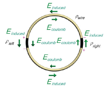
Source: Belcher's note available on Electroboom's channel
So... is Belcher ignoring the obvious? Is he doing something rather stupid?
Wanna see another professor doing the same as Belcher, and Lewin? Micheal Melloch of Purdue University - the same Micheal Melloch whose videos Jesse Gordon has linked in the comments of his videos on Lewin's ring. Too bad he is doing what Lewin (and Belcher!) is doing:QuoteFaraday's Law Example 4 (Electromagnetic Induction)
This is the fourth of four examples of the application of Faraday's Law. A current is ramped in a solenoid to produce circles of electric field intensity around the solenoid. The solenoid is surrounded by a conducting ring where the left half of the ring has a higher conductivity than the right half of the ring. What is observed is charge buildup at the boundaries between the two materials.
The charge buildup at the boundaries between the materials is what you KVLers are unable to see.
It's like glass for birds, or storks.
-
You are the one who believe Maxwell is infallible and his Treatise is gospel. I simply pointed out that the Treatise reflects the time it was written. A time where Maxwell's equations as we know them were yet to be penned. A time where people, including Maxwell, believed in the luminiferous ether. You have quoted a passage of the Treatise where Maxwell is illustrating the sources of emf as known at the time, so what? He states explicitly:
Interesting. Maxwell is fallible, but Lewin, whom struggles to solve the simplest of circuits, is infallible them!
Again with the boogeman Lewin. He is not alone in correctly applying Faraday. There are so many other professors, including Belcher, that do what Lewin does: accounting for both the EMF contribution of the induced field Eind and the scalar potential difference of the conservative field Ecoul. And, being human, the are fallible too.
But at this point in time they can base their view of classical electrodynamics on about 150 years of careful refinement by some of the most brilliant minds of the whole planet. So, I'll take that above what Maxwell (which was an absolute genius, but was also pioneering a new field) had to say in 1865. The ether is one glaring example.
A more refined view of classical electrodynamics in a less glaring one, and in fact...QuoteAlso, according to Maxwell (and he says it explicitly) Faraday's law is NOT a generalization of KVL. "Electromagnetic induction, the laws of which we shall afterwards examine" is just one more EMF that must be added to other EMFs when using KVL, "whatever be the origin of the force".
...you fail to see why we should move forward from the interpretations field theory at the time of the Americal Civil War.QuoteSo, according to your logic in Lewin's ring, the wire on the top has half the induced EMF and the wire at the bottom has half the induced EMF. So, can you now can compute the voltage VAD?
There is the EMF contribution of Eind, but there is also the scalar potential contribution of Ecoul. And guess what? The pretty much cancel each other in the conductor leaving an almost zero net electric field inside. Perfectly compliant with Ohm's law. The same superposition leaves a perfectly Ohm compliant resultant E field in both resistors. But being the resistance different, the field inside will be different as well.
Now, let's do 2+2: on branch 1 we have 0 field in the upper arc of conductor, strong E1 field inside the R1 resistor, and 0 field in the lower arc of conductor. The voltage is the same as that along the resistor alone: Vad1 = E1*deltaL, where deltaL is the length of the resistor.
In branch 2, for the same reasons we have Vad2 = E2*deltaL.
Since the net electric field is different in the two resistors, we get Vad1 != Vad2Quotenote I also wonder... what if the circuit has more than one loop linking dB/dt... What single one loop would you choose to compute the one and only value of Vad?
Then you use KVL and KCL to the complete and correct circuit to compute...
Sure, you use KVL to prove KVL. -
Wanna see another professor doing the same as Belcher, and Lewin? Micheal Melloch of Purdue University - the same Micheal Melloch whose videos Jesse Gordon has linked in the comments of his videos on Lewin's ring. Too bad he is doing what Lewin (and Belcher!) is doing:
QuoteFaraday's Law Example 4 (Electromagnetic Induction)
This is the fourth of four examples of the application of Faraday's Law. A current is ramped in a solenoid to produce circles of electric field intensity around the solenoid. The solenoid is surrounded by a conducting ring where the left half of the ring has a higher conductivity than the right half of the ring. What is observed is charge buildup at the boundaries between the two materials.
The charge buildup at the boundaries between the materials is what you KVLers are unable to see.
It's like glass for birds, or storks.
Excellent, I was waiting for something like this. Now, here is a question for you: what would happen if you replace the resistors with capacitors. Say, instead of the 100 ohm resistor place a 100nF capacitor, and instead of the 900 ohm resistor place a 10nF capacitor. What would be the voltage between nodes A and D, VAD at steady state? Spoiler alert: I did that experiment a few weeks ago and it looks very, very bad for team Lewin! -
Wanna see another professor doing the same as Belcher, and Lewin? Micheal Melloch of Purdue University - the same Micheal Melloch whose videos Jesse Gordon has linked in the comments of his videos on Lewin's ring. Too bad he is doing what Lewin (and Belcher!) is doing:
QuoteFaraday's Law Example 4 (Electromagnetic Induction)
This is the fourth of four examples of the application of Faraday's Law. A current is ramped in a solenoid to produce circles of electric field intensity around the solenoid. The solenoid is surrounded by a conducting ring where the left half of the ring has a higher conductivity than the right half of the ring. What is observed is charge buildup at the boundaries between the two materials.
The charge buildup at the boundaries between the materials is what you KVLers are unable to see.
It's like glass for birds, or storks.
Excellent, I was waiting for something like this. Now, here is a question for you: what would happen if you replace the resistors with capacitors. Say, instead of the 100 ohm resistor place a 100nF capacitor, and instead of the 900 ohm resistor place a 10nF capacitor. What would be the voltage between nodes A and D, VAD at steady state? Spoiler alert: I did that experiment a few weeks ago and it looks very, very bad for team Lewin!
This is another common trait of believers: once they are cornered, they change the topic to something new, so that the debunking has to start from scratch again and they can bask in the illusion that this time they could be right.
First is the ring with two resistors joined by conductors. Then the ring with two resistors and a battery. Then the ring with two resistors without conductors in between. Then the uniform resistive ring. Then the perfectly conducting ring. I have seen in the other thread the ring with a transistor in the loop. Now it's the two capacitors in a loop. What is next? A Josephson junction?
Two capacitors in a loop can lead to some nasty paradoxes. Will this invalidate the easily explained ring of just two resistors? Logic dictates that no, it won't. But believers are renowned for not being very good in applying logic.
-
The pretty much cancel each other in the conductor leaving an almost zero net electric field inside.
Right there is where you are wrong! In Lewin's ring the the induced emf is evenly distributed in the conductors and resistors. He failed to include that emf in the equivalent circuit, that is why he incorrectly concluded that KVL doesn't work. Once again: under the influence of a varying magnetic field a piece of conductor must be modeled as an equivalent voltage source in series with a resistance (or more generally an impedance). The voltage of of the source is derived from the induced emf, and the resistor (or impedance) is derived from the properties of the conductor. By the way, the same applies to anything that 'conducts': wires, resistors, inductors, and even capacitors!QuoteThen you use KVL and KCL to the complete and correct circuit to compute...
Sure, you use KVL to prove KVL.
Nope, you use a voltage measuring instrument to prove KVL. But of course, in order to do that, you must know how to use the instrument!