-
I have a simple challenge for team 'Lewin'. But before I do so, let me summarize the results presented by Lewin in the original experiment.
The first attached figure shows a diagram of Lewin's original experiment, including the measuring setup with the measuring wires tightly placed close to the one loop ring. R1 is 100 ohms and R2 is 900 ohms. Assume the induced EMF is 80 mV; if we disregard the resistance of the green wires, the calculated voltage V1 is -8 mV and the calculated voltage V2 is 72 mV. I think both team Lewin and team KVL agree on that. Do we also agree that the left 'voltmeter' shows -8 mV for Vx and the right 'voltmeter' shows 72 mv for Vy? Team KVL thinks that Vx=V1 and Vy=V2 because the voltage induced in the measuring wires cancels out the voltage induced in the corresponding section of the one loop ring, and KVL works just fine. Team Lewin thinks that Vx is not equal to Vy because KVL doesn't work, so that the voltage measured between nodes A and D shows different values depending if its taken from the left or from the right.
Now consider the circuit of the second attached figure, where the original single loop ring is replaced with a three loop ring with the same diameter as the original one loop ring. This arrangement of three loops has R1, R2, node A, and node D in the same locations as the original ring. In the figure, the three rings are separated so it is easier to see how they relate to each other, but in reality they are tightly pack together, with virtually no gap between the three green wire loops. Once again we have the measuring wires placed tightly close to the ring and R1 is 100 ohms, R2 is 900 ohms, and since we have three loops now, the induced EMF is 240 mV. This is the challenge: Calculate V1, V2, Vx, and Vy.
(An easy way of making a three loop ring is by making a one loop ring with three times the radius and then fold this bigger ring over itself three times so to end up with three concentric rings with the same radius as the original one loop ring.)
-
You realize of course both sides feel the same way about the other side, right?
There are no sides here.
That KVL doesn't hold under varying magnetic fields is an established fact, experimentally confirmed and predicted by the theory. We are not siding with Lewin or anyone or anything. -
You realize of course both sides feel the same way about the other side, right?
There are no sides here.
That KVL doesn't hold under varying magnetic fields is an established fact, experimentally confirmed and predicted by the theory. We are not siding with Lewin or anyone or anything.
Really, a established fact? Are you implying that the problem I just posted above has no theoretical solution by using KVL because the induced EMF comes from a varying magnetic field? Or that the theoretical solution obtained with KVL will not match the experimental results? The only established fact so far is that bsfeechannel has no idea of what he is talking about!!! -
No, says the guy who uses Faraday's law and not KVL, but you can't tell the difference.Oh, goodness me. What a wondrous, copious and melliflously superfluous word salad. All to hide the fact that you cannot lump Lewin's ring. Here, let me repeat the question you are so eloquently avoiding to answer.
Says the guy that when solving Lewin's ring, the first thing he does is to lump the EMF, and then he follows up by using KVL to find the voltages in the resistors!
A rose by any other name is still a rose! You are the one that can not tell they are the same...
You see Sredni? They understand that their claim that KVL, the real KVL, always holds is false. Haven't I told you? But to save face they're now calling Faraday's law KVL.
-- 2+2 = 5.
-- No, two plus two equals four.
-- Yeah, that's what I wrote.
-- No you wrote two plus two equals five.
-- No, I didn't.
-- Yes, you did. How to you call this number: 5?
-- Four. -
No, says the guy who uses Faraday's law and not KVL, but you can't tell the difference.Oh, goodness me. What a wondrous, copious and melliflously superfluous word salad. All to hide the fact that you cannot lump Lewin's ring. Here, let me repeat the question you are so eloquently avoiding to answer.
Says the guy that when solving Lewin's ring, the first thing he does is to lump the EMF, and then he follows up by using KVL to find the voltages in the resistors!
A rose by any other name is still a rose! You are the one that can not tell they are the same...
You see Sredni? They understand that their claim that KVL, the real KVL, always holds is false. Haven't I told you? But to save face they're now calling Faraday's law KVL.
-- 2+2 = 5.
-- No, two plus two equals four.
-- Yeah, that's what I wrote.
-- No you wrote two plus two equals five.
-- No, I didn't.
-- Yes, you did. How to you call this number: 5?
-- Four.
You should be asking Sredni for help on how to solve the problem I posted above
https://www.eevblog.com/forum/amphour/562-electroboom!/msg3840656/#msg3840656
because I am pretty sure you lack the capacity to even attempt to solve it.
-
I have a simple challenge for team 'Lewin'.
It's not team 'Lewin'. It's team 'Classical Electrodynamics'.
But what's the point of the exercise?
Both 'teams' are doomed to find the same values for what is read by the voltmeters.
Anyway, if I copied it correctly - and there is no guarantee I did with all those turns making me dizzy - I would say
Vr1 = -24mV, Vr2 = +216mV
Vm1 = -136 mV, Vm2 = -56 mV
Provided I counted the 'rings' right and didn't change some sign here and there.
And if I got one sign wrong somewhere, that would proof that there can be say 200 mV in two inches of copper wire that carry a current of 100 nA?
Excellent! You got the correct results. Now, what is the voltage between nodes A and D, VAD? -
Excellent! You got the correct results. Now, what is the voltage between nodes A and D, VAD?
I didn't find a way to make it glow, but let's see...
IT DEPENDS ON THE PATH.
-
Excellent! You got the correct results. Now, what is the voltage between nodes A and D, VAD?
I didn't find a way to make it glow, but let's see...
IT DEPENDS ON THE PATH.
No it doesn't depend on the path, because we are calculating it. You can use either the voltage measured from the left or the voltage measured from the right to find exactly the same voltage between nodes A and D, VAD. -
The only established fact so far is that bsfeechannel has no idea of what he is talking about!!!
C'mon, man! There's no shame in being wrong. You can bet your bottom dollar that all of us held at some time in the history of our lives the same misconceptions you and Jesse Gordon are now expressing. We normally get aware of voltages when we poke circuits with the probes of our meters and we have this intuitive, but misleading, perception that voltages are generated by the components. What components do is to shape the conditions in which the electromagnetic field exists in that region of the space. Voltages are the consequence of the existence of the fields. Once you switch your "paradigm" to think in terms of fields--not just circuits--you immediately expand the capabilities of your analyses.
For some of us, the shift is very difficult. But it is worth it.
-
The only established fact so far is that bsfeechannel has no idea of what he is talking about!!!
C'mon, man! There's no shame in being wrong. You can bet your bottom dollar that all of us held at some time in the history of our lives the same misconceptions you and Jesse Gordon are now expressing. We normally get aware of voltages when we poke circuits with the probes of our meters and we have this intuitive, but misleading, perception that voltages are generated by the components. What components do is to shape the conditions in which the electromagnetic field exists in that region of the space. Voltages are the consequence of the existence of the fields. Once you switch your "paradigm" to think in terms of fields--not just circuits--you immediately expand the capabilities of your analyses.
For some of us, the shift is very difficult. But it is worth it.
Sure, now use your vast knowledge of electromagnetic fields and help Sredni calculate the voltage VAD from the problem above. -
If you honestly answer the above questions and I'll do my best to draw up Lewin's loop and show how I would measure the voltage across the half turns.
Oh, no. Now you answer MY question, not a question of your choice.
And my question is:
This is Lewin's ring: two resistors in a single loop that goes around a circular region (let's consider it of the same size as the loop, so you can see there is no 'room to twist' the wires) of variable magnetic field. The resistors are required to be on the opposite sides of the variable magnetic field region.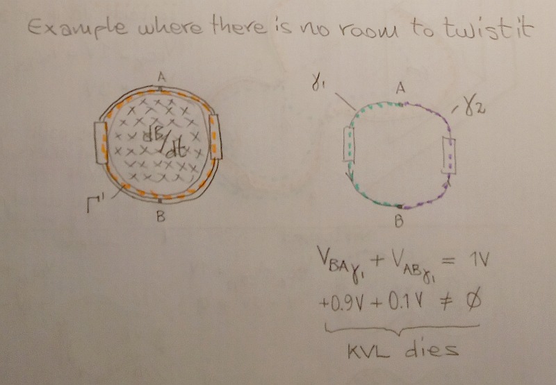
https://i.postimg.cc/kX0TSBw6/Lewin-ring-is-unlumpable.jpg
Please, show everybody you can draw a circuit path (make it green, meaning it's 'flux-free') that joins the resistors' terminals to the "lumped transformer secondary" terminals and DOES NOT INCLUDE the variable magnetic field region in its interior. Like I did for the lumpABLE circuit I decided to see as lumpED (in my post "Lumpable (lumped and not lumped) and not lumpable circuits for dummies").
In addition, you can also show everybody you can draw the path inside your "lumped transformer secondary" that DOES INCLUDE the variable magnetic field region (make it orange) but IS NOT part of the green circuit path.
I will show you that if you can do that you will run into contradiction.
OK here's how anybody can unambiguously physically measure the induced voltage in half of an air-core transformer secondary turn: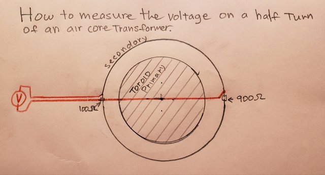
I did not draw volt meters for the resistors because measuring the voltage across those is simple.
The red wires represent a path on a plane which (ON THAT PLANE) do not contain a non-conservative field. SO LONG AS THE RED WIRES ARE ON THAT PLANE, the path does not matter.
That plane passes through the entire center of the primary solenoid winding. Any paths ON THAT PLANE are path-independent.
You may consider the size of the resistors as zero to make things simple, but the reality is that the resistors occupy a small section of the arc and thus are actually resistors with a small series bit of induced voltage, and the half-turns are actually slightly less than half-turns in series with a small amount of resistance, which is actually always how we model both of those components for high accuracy simulations.
But considering the resistors to have zero length and the half turns to have exactly half a turn and no resistance simplifies things for this discussion and does not really change the point we're arguing about. So be diversionary if you want but that's what we got.
~~~~~~~
I guess since you're moving on to Lewin's air core solenoid setup you've given up on toroidal and E-Core transformers because you realize they DO in fact hold fine with KVL?
For example in the diagram below, if I were to actually construct and measure with a volt meter the voltage differences across each element in the places indicated by V1 through V5, would the sum be zero?
For clarity I have drawn the idiot screen to signify that I am not allowing the number or configuration of transformer turns to be modified during the midst of the experiment. Ya know what I mean?
I think you cannot deny that Σ(V1,V2,V3,V4,V5) = 0.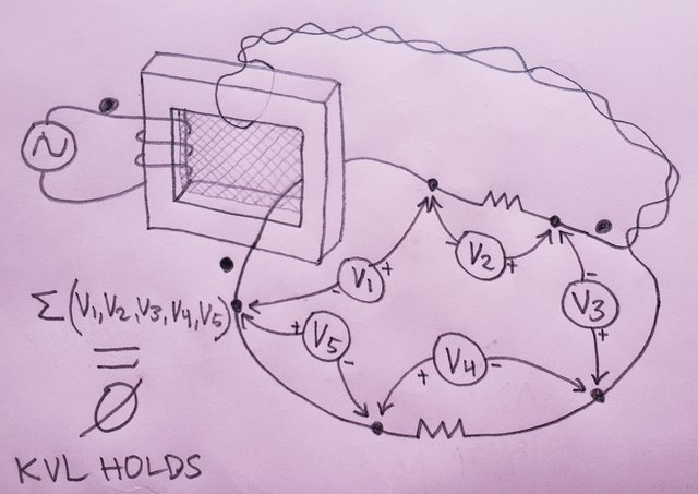
https://i.postimg.cc/jdJntBXT/20211128-121506.jpg
Now tell me please, regarding the elements POINTED TO BY V1 through V5 above, which of them is not unambiguously physically measurable with a volt meter?
According to your trusted source below, if the voltage across the elements can all be unambiguously physically measured, then KVL will hold.
https://i.postimg.cc/sf4j3HbF/Desoer-Kuh.jpg
How can you deny that KVL is failing to hold in my "KVL HOLDS" diagram above?
Do you really think that Σ(V1,V2,V3,V4,V5) ≠ 0 as measured in real life?
Please explain EXACTLY why you think KVL is failing if you think KVL is failing to hold in my above diagram.
Will the volt meters not all sum to zero? Or will they sum to zero giving the appearance that KVL holds, but for some technical reason you say it's still not holding?
If you only answer one thing, please let it be this:
Q: Do you believe the volt meters in my "KVL HOLDS" diagram above will sum to zero? -
You realize of course both sides feel the same way about the other side, right?
There are no sides here.
That KVL doesn't hold under varying magnetic fields is an established fact, experimentally confirmed and predicted by the theory. We are not siding with Lewin or anyone or anything.
Wow, do you know how weak of an argument that be?
Watch:
"Yeah, there no sides, I'm right and you're wrong.
KVL holds fine under varying magnetic fields as an established fact, experimentally confirmed by my Lewin Clock and predicted by theory.
I'm not siding with anyone or anything, you're just wrong."
Do you see how little that attitude actually does for the discussion?
Why not put your powers of experimentally confirmed predictive theory to work and answer this one question:
In the below diagram, will Σ(V1,V2,V3,V4,V5) = 0 as measured in real life by a volt meter?
In the above diagram, will Σ(V1,V2,V3,V4,V5) = 0 as measured by a volt meter in real life?
A simply yes or no would be not only much appreciated but a lack of one will show your lack of understanding.
There's nothing complex, it's a transformer with a couple secondary one-turn windings, connected in a loop with two resistors. Easily constructed, and easily measured.
What is your prediction? Will Σ(V1,V2,V3,V4,V5) = 0, as measured by real volt meters in a real world test? Yes or not, please if you can! -
Oh boy, where to even begin...
Okay, first of all: I'm not in denial of observable reality.
Excellent!
So tell me please if you can, will Σ(V1,V2,V3,V4,V5) = 0 in the below diagram as measured with real volt meters in a real world test?
https://i.postimg.cc/jdJntBXT/20211128-121506.jpg
Thank you! -
No it doesn't depend on the path, because we are calculating it.Excellent! You got the correct results. Now, what is the voltage between nodes A and D, VAD?
I didn't find a way to make it glow, but let's see...
IT DEPENDS ON THE PATH.
It's like trying to explain color to someone who is blind since birth.
I have already calculated "VAD" twice: its value depends on the path.
On the path set by the first voltmeter I get -136mV; on the path set by the second voltmeter I get -56mV.
I can compute on any path I want, if I know how the dB/dt region is partitioned by the path itself. Do you have any idea how easy it is for me to compute it? The only difficulty is making sure I am following that spiral labyrinth you set up hoping to get us confused.
Now, I solved your challenge.
Will you solve a few very elementary problems I pose? Or will you evade my questions as Jesse Gordon is doing? -
OK here's how anybody can unambiguously physically measure the induced voltage in half of an air-core transformer secondary turnIf you honestly answer the above questions and I'll do my best to draw up Lewin's loop and show how I would measure the voltage across the half turns.
Oh, no. Now you answer MY question, not a question of your choice.
And my question is:
This is Lewin's ring: two resistors in a single loop that goes around a circular region (let's consider it of the same size as the loop, so you can see there is no 'room to twist' the wires) of variable magnetic field. The resistors are required to be on the opposite sides of the variable magnetic field region.
https://i.postimg.cc/pLmfyHxZ/Lewin-ring-is-unlumpable.jpg
Please, show everybody you can draw a circuit path (make it green, meaning it's 'flux-free') that joins the resistors' terminals to the "lumped transformer secondary" terminals and DOES NOT INCLUDE the variable magnetic field region in its interior. Like I did for the lumpABLE circuit I decided to see as lumpED (in my post "Lumpable (lumped and not lumped) and not lumpable circuits for dummies").
In addition, you can also show everybody you can draw the path inside your "lumped transformer secondary" that DOES INCLUDE the variable magnetic field region (make it orange) but IS NOT part of the green circuit path.
I will show you that if you can do that you will run into contradiction.
Nice try, but you did not answer the question.
Let me repeat it for you here, in case you missed:
This is Lewin's ring: two resistors in a single loop that goes around a circular region (let's consider it of the same size as the loop, so you can see there is no 'room to twist' the wires) of variable magnetic field. The resistors are required to be on the opposite sides of the variable magnetic field region.
https://i.postimg.cc/pLmfyHxZ/Lewin-ring-is-unlumpable.jpg
Please, show everybody you can draw a circuit path (make it green, meaning it's 'flux-free') that joins the resistors' terminals to the "lumped transformer secondary" terminals and DOES NOT INCLUDE the variable magnetic field region in its interior. Like I did for the lumpABLE circuit I decided to see as lumpED (in my post "Lumpable (lumped and not lumped) and not lumpable circuits for dummies").
In addition, you can also show everybody you can draw the path inside your "lumped transformer secondary" that DOES INCLUDE the variable magnetic field region (make it orange) but IS NOT part of the green circuit path.
I will show you that if you can do that you will run into contradiction.
Please, please, please, do not fly to another galaxy with your armchair before answering it. -
Sure, now use your vast knowledge of electromagnetic fields and help Sredni calculate the voltage VAD from the problem above.
My "vast knowledge" won't help you. I asked the same questions long ago, got the right answers, but ended up like you: confused.
I can show you the door to your enlightenment, but I can't walk you through it. You'll have to do it yourself. -
It's like trying to explain color to someone who is blind since birth.
I have already calculated "VAD" twice: its value depends on the path.
On the path set by the first voltmeter I get -136mV; on the path set by the second voltmeter I get -56mV.
I can compute on any path I want, if I know how the dB/dt region is partitioned by the path itself. Do you have any idea how easy it is for me to compute it? The only difficulty is making sure I am following that spiral labyrinth you set up hoping to get us confused.
Now, I solved your challenge.
Will you solve a few very elementary problems I pose? Or will you evade my questions as Jesse Gordon is doing?
You have solve nothing! For a moment I thought you knew how to solve circuits, but then you come with such a ridiculous argument. Do you even know what a 'node' is? Of course I was expecting you to come with some sort of excuse, but this is plainly denial! I see now that trying to reason with you is impossible. For everyone else reading, I'll now show how to get the solution, and how simple it is to compute the voltage between the nodes A and D, VAD, a process that was not done correctly in Lewin's presentation.
In the problem I posted above the total generated EMF is 240mV. Using KVL we now compute the loop current as:
\$
I = \frac{{EMF}}{{R_1 + R_2 }} = \frac{{240mV}}{{100\Omega + 900\Omega }} = 0.240mA
\$
Now we can compute the voltage drop in each resistor:
\$
\begin{array}{l}
V_2 = R_2 \cdot I = 900\Omega \cdot 0.240mA = 216mV \\
V_1 = - R_1 \cdot I = - 100\Omega \cdot 0.240mA = - 24mV \\
\end{array}
\$
To solve for Vx and Vy we need to find an equivalent circuit to work with. We know that three wire loops are generating 240mV. So each quarter of a loop can be lumped as a voltage source of 240mV/(3*4)=20mV. We now notice that the '+' terminal of R1 is 3/4 loop (or a 60mV voltage source) from node 'D' and the '-' terminal of R1 is also 3/4 loop (or a 60mV voltage source) from node 'A'. Similarly the Vx 'voltmeter' is 1/4 loop (or a 20mV voltage source) from node 'A' and 1/4 loop (or a 20mV voltage source) from node 'D'. The same can be said to R2 and the Vy 'voltmeter'. Being very careful with the signs, this is the equivalent circuit we need: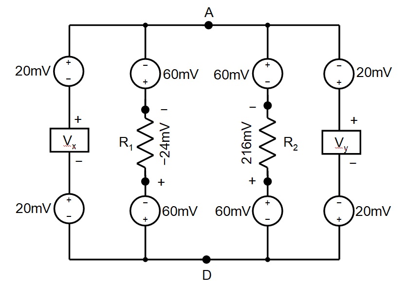
To solve for Vx, we apply KVL to the left loop:
\$
V_x = - 20mV - 60mV - ( - 24mV) - 60mV - 20mV = - 136mV
\$
To solve for Vy, we apply KVL to the right loop:
\$
V_y = 20mV + 60mV - 216mV + 60mV + 20mV = - 56mV
\$
Finally, to find VAD, we can calculate it in four different ways from the equivalent circuit above by applying KVL to each one of the four branches between nodes A and D:
\[
\begin{array}{l}
V_{AD} = 20mV + ( - 136mV) + 20mV = - 96mV \\
V_{AD} = - 60mV - ( - 24mV) - 60mV = - 96mV \\
V_{AD} = 60mV - 216mV + 60mV = - 96mV \\
V_{AD} = - 20mV + ( - 56mV) - 20mV = - 96mV \\
\end{array}
\]
So how many values we have for VAD? Just one: -96mV.
I assembled and tested this circuit. The voltages I measured are V1=-24.4mV, V2=212mV, Vx=-134mV, Vy=-56mV, and VAD=-96mV, as shown in the attached oscilloscope captured images. As you can see, the theory and the measurements are a very good match!
I know, I know: Almost a perfect match from theoretical computations and experimental results mean nothing for team Lewin. For everyone else, here is the evidence, once again, that KVL works perfectly for circuits under the influence of varying external magnetic fields and that Lewin did NOT get his calculations correct in his presentation because he ignored the induced voltages in the wires when he extracted the equivalent circuit.
-
Sure, now use your vast knowledge of electromagnetic fields and help Sredni calculate the voltage VAD from the problem above.
My "vast knowledge" won't help you. I asked the same questions long ago, got the right answers, but ended up like you: confused.
I can show you the door to your enlightenment, but I can't walk you through it. You'll have to do it yourself.
Here, go argue with results:
https://www.eevblog.com/forum/amphour/562-electroboom!/msg3842183/#msg3842183
-
It's like trying to explain color to someone who is blind since birth.
I have already calculated "VAD" twice: its value depends on the path.
On the path set by the first voltmeter I get -136mV; on the path set by the second voltmeter I get -56mV.
I can compute on any path I want, if I know how the dB/dt region is partitioned by the path itself. Do you have any idea how easy it is for me to compute it? The only difficulty is making sure I am following that spiral labyrinth you set up hoping to get us confused.
Now, I solved your challenge.
Will you solve a few very elementary problems I pose? Or will you evade my questions as Jesse Gordon is doing?
You have solve nothing!
---snip---
It's a no, then?
You confirm will evade questions just like Jesse has done till now?
By the way: your challenge wasQuoteThis is the challenge: Calculate V1, V2, Vx, and Vy.
I calculated them (it took me some six-seven minutes, mostly to decide to get off the couch and find paper and pencil, and to make sure I had copied the spirals right), and you said it yourself:QuoteExcellent! You got the correct results.
And now you are on your victory lap as if you were the only one to get the correct results. (And all this after I wrote, in the same message I posted the solution in: "Both 'teams' are doomed to find the same values for what is read by the voltmeters."
Go figure.
I wonder if 'everyone else reading' should be made aware that your solution forecasts that a copper wire a few inches long will drop 20 mV when a current of 0.24 mA flows through it. But hey, you have tiny little batteries in your wires, right? Like they explained coils in high school.
So, to be clear, you won't try to solve the simple circuit quizzes I pose?
You must be the kind of guy than never pays up when he loses a bet.
Once again, what is the value of VAD? Go argue with results:
https://www.eevblog.com/forum/amphour/562-electroboom!/msg3842183/#msg3842183
-
Once again, what is the value of VAD?
Once again:
It depends on the path.
How did place the probes to measure it? Midway through the disk, because you chose an highly symmetrical setup?
How would you place the probes if the solenoid generating the field was made in triangular shape and the three-turn ring with the resistors was shaped as Mickey Mouse's head silhouette, tilted and off-center?
-
Once again, what is the value of VAD?
Once again:
It depends on the path.
How did place the probes to measure it? Midway through the disk, because you chose an highly symmetrical setup?
How would you place the probes in the solenoid was made in triangular shape and the ring with the resistor shaped as Mickey Mouse's head silhouette, tilted and off-center?
Nope, the voltage VAD is ALWAYS -96mV. I asked you to calculate it, not to measure it. For this particular configuration of the problem, it is fairly easy to setup the probe so that the external magnetic field does not induce a voltage on it. The calculation perfectly matches the measurement. When Lewin did his experiment with a similar shape, he did not extract the correct equivalent circuit, and then he couldn't figure out what VAD was, so he blamed KVL. -
You must be the kind of guy than never pays up when he loses a bet.
KVLers are pathetic, to say the least. -
Once again, what is the value of VAD? Go argue with results:
https://www.eevblog.com/forum/amphour/562-electroboom!/msg3842183/#msg3842183
I don't argue with data rigged to support pseudo scientific claims.