-
If you assume the voltage between nodes A and D, VAD, is unique at some instant of time (which by the way it is true), can you calculate that voltage?
Don't bother. Usual tactics of cultists - to simply ignore anything that would somehow let them agree with you.
In case of 1V EMF, resistors 100 and 900 Ohms, 1mA current is flowing through loop. Voltage on resistors 0.1V and 0.9V accordingly. So far everybody agree.
Lewin's cultists truly believe that 1/4 of the transformer wire turn do not have 1/4 of EMF on it because when they try to measure using voltmeter, by placing voltmeter leads next to wire they measure, they see 0V - as expected. It is obvious that Faradays' law of induction do not care - it is test circuit or voltmeter leads, but Lewin's cultists are stubborn, they claim that they know better and for some reason voltmeter leads are not influenced by time-varying magnetic field of experiment, only circuit. In short - fact that Lewin and his cultists struggle to properly measure EMF, do not mean it does not exist.
Back to the voltage between A-D: If circuit is symmetric, all four wires of the circuit loop equal length, resistors so small that we ignore EMF inside them, then each wire receives 1/4 of EMF, 1V/4 = 0.25V. Voltage between A and D will be +0.25V-0.1V+0.25V = 0.4V if calculated using 100 Ohm resistor side. Also we can calculate voltage using 900 Ohm resistor side, -0.25+0.9V-0.25=0.4V.
If we try to measure voltage between A-D, by orienting probe leads along the circuit loop, each probe lead will receive +0.25V or -0.25V EMF depending on which side of the solenoid they are. If we put voltmeter and it's leads on one side of solenoid, then we see 0.4V-0.25V-0.25V = -0.1V, on the other side we will see 0.4V+0.25V+0.25V=0.9V. Visualization of what I am telling, attached.
-
As you are claiming that this is recursive - you shall not have any difficulties of finding post with answer to this ever repeating question.
Oh, now I see the tactic clearly.
I remember the exact post quite well - Sredni calculated, IIRC, six different values, one of which matched jesuscf's expectation. jesuscf definitely saw it, and remembers it (assuming he doesn't have actual brain damage, which is, I think, a fair assumption).
But, I have "any difficulties" finding it. 33 pages of smoke screens and bullshit burying it so deep I can't find it. Tried to look it up, gave up. Sheer number of pages prevents the "show all pages" feature, preventing successful text search. It is simply too much work. Besides, if I look it up, this will result in nothing but more smoke screens. Your whole tactic is to just waste others time.
See? Now you can claim your victory.
I didn't know you are this dirty. I'm sad for you. Goodbye. -
As you are claiming that this is recursive - you shall not have any difficulties of finding post with answer to this ever repeating question.
Oh, now I see the tactic clearly.
Tactic? Victory? Geez You may consider to cool down.
When you reply to someone "I told you long time ago" - perhaps you both know what you are talking about. Problem is that this is not private chat room for you two, this is public forum, huge thread with 30+ pages indeed. There are other readers, many most likely did not read every post. Be courteous to at least newcomers interested in the subject or whatever they find in this thread. -
.
-
Now, please, tell us what those values are.
Time to put up or shut up.
What you are trying to do here is the good old "moving-the-goalposts" fallacy. You are trying to distract from the original question; your plan is not going to work.
Back to Lewin's circuit which is perfectly symmetric, with no extra 'dashed' paths. Let us concentrate on that fixed circuit, with no extra wires of any kind. If you assume the voltage between nodes A and D, VAD, is unique at some instant of time (which by the way it is true), can you calculate that voltage?
You remind me of that guy who claimed he could read.
But he could only read from his own only book. Not other books.
Hic Rhodus, hic salta.
What happened to your beautiful theory? It only applies to circular concentric setups? -
Yes I was expecting to continue discussion with Sredni or bsfeechannel, not you. As soon as Lewin's followers agree that path-dependency can be proven using multiple windings of measurement wire which are essentially another secondary winding on transformer
But are they?
The other winding has the voltmeter's internal resistance embedded into it. Do you really think it is equivalent to another secondary winding of a transformer?
If I put a loop of wire around a core with an EMF of 1V I can get 1V across a load of say 10 ohms and 100 mA flowing in it.
If I put a loop formed by my voltmeters and its two probes around a core with an EMF of 1V and I attach the prove tips to a 10 ohms load... what do I get? Still 1V across the load? Still 100 mA flowing through it?
No?
Why not?
Ah, now you consider the internal resistance of the voltmeter a second load?
But are you sure there is a net voltage across the wires?
Look what happens to the charge when you short the voltmeters tips around a core:
You can see it by putting some numbers (I used 1mohm for the short and 10Gohm for the open to get nice numbers, but feel free to put actual values if you wish.
Well, that charge that has changed place is what kills the 'induced voltage' in the conducting arcs. You need to study a bit to understand why. Here's a hint for you: "superposition".
Regarding path depedency and how to measure the voltage ALONG a coil, it's obvious that it's easier to show it for a single coil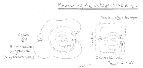

why bothering adding the unnecessary complication of multiple loops? They will only make pictures harder to draw and follow, but the concept will still be the same: making sure there is no dB/dt region in the measurement loop. And besides, a KVLer will be in the same position if they were asked to show a picture that illustrates their 'path-independent' measure for a multiloop transformer with multiple layers of windings. What do you do? Drill through the core and the other wires?
-
Now, please, tell us what those values are.
Time to put up or shut up.
What you are trying to do here is the good old "moving-the-goalposts" fallacy. You are trying to distract from the original question; your plan is not going to work.
Back to Lewin's circuit which is perfectly symmetric, with no extra 'dashed' paths. Let us concentrate on that fixed circuit, with no extra wires of any kind. If you assume the voltage between nodes A and D, VAD, is unique at some instant of time (which by the way it is true), can you calculate that voltage?
You remind me of that guy who claimed he could read.
But he could only read from his own only book. Not other books.
Hic Rhodus, hic salta.
What happened to your beautiful theory? It only applies to circular concentric setups?
What I described applies to any circuit! It may not be easy but it is doable! I will not be distracted with a harder problem because that is your tactic. Let us concentrate in easy symmetric setups like Lewin's circuit, the one where he says KVL doesn't work. Did you figure out how to calculate VAD yet? You may want to read the post from Ogden, he explains it clearly, and it is very easy.
By the way, where are the calculations for the two capacitor problem? It looks to me that you used SPICE to solve that one. How did you represent the induced EMF in the equivalent circuit?
-
.
-
What I described applies to any circuit! It may not be easy but it is doable! I will not be distracted with a harder problem because that is your tactic. Let us concentrate in easy symmetric setups like Lewin's circuit, the one where he says KVL doesn't work. Did you figure out how to calculate VAD yet? You may want to read the post from Ogden, he explains it clearly, and it is very easy.
Apparently he figured it out. Here: https://www.eevblog.com/forum/amphour/562-electroboom!/msg3927425/#msg3927425
Can you explain us where is his calculation wrong?
I have seen Ogden's calculations, but such calculation relies heavily on symmetry. Albeit knowing that it may be harder, how is that calculation applied to a non symmetric circuit?
Regards.
There is only one answer. The voltage VAD is unique, because there is only one path to consider, the path of the circuit. Sredni keeps saying that the voltage is path dependent, with made up paths that don't follow the circuit, and them he proceeds to calculate infinite answers because he has infinite made up paths.
The real question here should be: will KVL work on an loop that is not circular with an asymmetrically placed magnetic flux? Of course it will! That is what Faraday's law tell us.
EDIT: Trevor Kearny has a really nice video with a very ingenious solution for a non-symmetric problem here:
Team Lewin should watch this video too, maybe they can learn something!
-
.
-
There is only one answer. The voltage VAD is unique, because there is only one path to consider, the path of the circuit.
Then how will you measure such VAD?The real question here should be: will KVL work on an loop that is not circular with an asymmetrically placed magnetic flux? Of course it will! That is what Faraday's law tell us.
Then how will you calculate VAD in an asymmetrical circuit?
It looks like I edited my post after you replied. Here, watch this video by Trevor Kearney:
-
Yes I was expecting to continue discussion with Sredni or bsfeechannel, not you. As soon as Lewin's followers agree that path-dependency can be proven using multiple windings of measurement wire which are essentially another secondary winding on transformer
But are they?
The other winding has the voltmeter's internal resistance embedded into it. Do you really think it is equivalent to another secondary winding of a transformer?
I do not see you are answering my question which was very SPECIFIC - about transformer with 100 turns of secondary winding. Also if you use voltmeter leads with resistance embedded into them - stop doing that! Get proper tools.
[edit] Same fallacy again and again. You can't draw mythical dotted line which separates circuit wires from probe wires and claim that Faradays's law of Induction stops where you choose:
Seems you missed this:
https://www.eevblog.com/forum/amphour/562-electroboom!/msg3913808/#msg3913808 -
Back to the voltage between A-D: If circuit is symmetric, all four wires of the circuit loop equal length, resistors so small that we ignore EMF inside them, then each wire receives 1/4 of EMF, 1V/4 = 0.25V. Voltage between A and D will be +0.25V-0.1V+0.25V = 0.4V if calculated using 100 Ohm resistor side. Also we can calculate voltage using 900 Ohm resistor side, -0.25+0.9V-0.25=0.4V.
How would you compute Vad if:- the circuit is not symmetric;
- and the four wires have different lengths.
I am glad you asked. Asymmetric to circuit/probe_leads magnetic field is outside of scope for Dr.Lewin's experiment, Thou jesuscf provided link to video explaining this problem.
In case you ask about calculation of voltage between two asymmetric points of Dr.Lewin's experiment, then it is not that hard. You can even try to solve it yourself. Let's say circumference of wire is 10cm, resistors still way much smaller so we ignore dimensions of both. We know that EMF induced is 1V meaning 0.1V per cm. Voltage on resistors still 0.1V and 0.9V. Let's say we move A&D points 0.5cm off-center to the right, in result we have two wires of 3cm with 100Ohms resistor on the left side and two wires 2cm each, with 900 Ohms resistor on right side of circuit loop. Voltage calculation using left side path would be +0.3-0.1+0.3=0.5V and -0.2+0.9-0.2=0.5V for right side path.
Zero wire on right side and 2*5cm on the left? - No problem! +0.5-0.1+0.5=0.9V on the left and -0.0+0.9-0.0=0.9V on the right. It also means measurement points are exactly on right side resistor terminals, so we can calculate answer using Ohms law U=IR as well.QuoteAnd also, how will you measure Vad (supposed that it is even possible to directly measure it)?
Measuring asymmetrical circuit is another can of worms which is, sorry again, outside of scope of Dr.Lewin's experiment, but I can tell you how to measure for (symmetric) Dr.Lewin's experiment: run voltmeter leads properly so magnetic flux do not impact them. There is only one way to run probe leads for Lewin's experiment - directly between AD, such a way that they split magnetic flux area in half, in case of symmetric circuit which Lewin's experiment for sure is. Mabilde not only tells how to do it but also shows it. -
Now, please, tell us what those values are.
Time to put up or shut up.
What you are trying to do here is the good old "moving-the-goalposts" fallacy. You are trying to distract from the original question; your plan is not going to work.
Back to Lewin's circuit which is perfectly symmetric, with no extra 'dashed' paths. Let us concentrate on that fixed circuit, with no extra wires of any kind. If you assume the voltage between nodes A and D, VAD, is unique at some instant of time (which by the way it is true), can you calculate that voltage?
You remind me of that guy who claimed he could read.
But he could only read from his own only book. Not other books.
Hic Rhodus, hic salta.
What happened to your beautiful theory? It only applies to circular concentric setups?
What I described applies to any circuit! It may not be easy but it is doable!
Oh, I know it is doable. Numerically. And Notaros, McDonald and Belcher know how to do it, as well.
But I believe most KVLers have no friggin' idea on how to do it.
Can you do it?QuoteI will not be distracted with a harder problem because that is your tactic.
No, my tactic is to show you that the EM method of using both the electrical scalar potential and the magnetic vector potential is not the brightest of the ideas when you are dealing with circuits. And if you were able to solve that problem you would know what Notaros and McDonald mean. And I could also show you how you do NOT use this method in every day life.QuoteLet us concentrate in easy symmetric setups like Lewin's circuit, the one where he says KVL doesn't work. Did you figure out how to calculate VAD yet?
See? I showed you so many VAD so many times that I've lost count. And you still pretend I didn't.QuoteBy the way, where are the calculations for the two capacitor problem? It looks to me that you used SPICE to solve that one. How did you represent the induced EMF in the equivalent circuit?
Do you really think it's that difficult to compute the reactances and use those instead of resistances?
Wow. To me, it's so easy it's basically a waste of time doing it.
But I will do it when you show me what are the actual voltages across the resistors and the probe wires in the circuit I've drawn.
Can't you do it? -
Now, please, tell us what those values are.
Time to put up or shut up.
What you are trying to do here is the good old "moving-the-goalposts" fallacy. You are trying to distract from the original question; your plan is not going to work.
Back to Lewin's circuit which is perfectly symmetric, with no extra 'dashed' paths. Let us concentrate on that fixed circuit, with no extra wires of any kind. If you assume the voltage between nodes A and D, VAD, is unique at some instant of time (which by the way it is true), can you calculate that voltage?
You remind me of that guy who claimed he could read.
But he could only read from his own only book. Not other books.
Hic Rhodus, hic salta.
What happened to your beautiful theory? It only applies to circular concentric setups?
What I described applies to any circuit! It may not be easy but it is doable!
Oh, I know it is doable. Numerically. And Notaros, McDonald and Belcher know how to do it, as well.
But I believe most KVLers have no friggin' idea on how to do it.
Can you do it?QuoteI will not be distracted with a harder problem because that is your tactic.
No, my tactic is to show you that the EM method of using both the electrical scalar potential and the magnetic vector potential is not the brightest of the ideas when you are dealing with circuits. And if you were able to solve that problem you would know what Notaros and McDonald mean. And I could also show you how you do NOT use this method in every day life.QuoteLet us concentrate in easy symmetric setups like Lewin's circuit, the one where he says KVL doesn't work. Did you figure out how to calculate VAD yet?
See? I showed you so many VAD so many times that I've lost count. And you still pretend I didn't.QuoteBy the way, where are the calculations for the two capacitor problem? It looks to me that you used SPICE to solve that one. How did you represent the induced EMF in the equivalent circuit?
Do you really think it's that difficult to compute the reactances and use those instead of resistances?
Wow. To me, it's so easy it's basically a waste of time doing it.
But I will do it when you show me what are the actual voltages across the resistors and the probe wires in the circuit I've drawn.
Can't you do it?
This video from Trevor Kearney debunks many, if not all your claims:
Have you watched it yet? Pay attention on how many potential difference voltages between nodes A and B he calculates: one.
EDIT: there is a typo in the video above. When calculating the voltage VAB, Trevor Kearney wrote -0.17202 but the correct calculation is:
VAB=0.3798V-(0.1 A x 5 ohm)=-0.1202V
-
I do not see you are answering my question which was very SPECIFIC - about transformer with 100 turns of secondary winding. Also if you use voltmeter leads with resistance embedded into them - stop doing that! Get proper tools.
Right. You have voltmeters with zero internal resistance. Where did you buy those? Duckburg?Quote[edit] Same fallacy again and again.
You can't draw mythical dotted line which separates circuit wires from probe wires and claim that Faradays's law of Induction stops where you choose:
You do not understand what you see. Any path you can imagine within that region of space will NOT be able to form a loop (with the branch of circuit you want to measure the voltage of) that will cut the variable flux. That is why KVL will work in that region of space.
In 2D it's easy to see it. In 3D the three-dimensional region of space will be more complicated, but you can still find it.QuoteSeems you missed this:
https://www.eevblog.com/forum/amphour/562-electroboom!/msg3913808/#msg3913808
Are those the zero internal resistance voltmeters? -
Are those the zero internal resistance voltmeters?
When measuring voltage what you want is infinite internal resistance voltmeters. Anyhow, I'll assume what you wrote is a typo.
For the BM869s: input impedance is 10Mohm in the mV range.
For the Fluke 187, directly from the user manual:
"When measuring voltage, the meter acts like a 10 MΩ
(10,000,000 Ω) impedance in parallel with the circuit. This
loading effect can cause measurement errors in high-impedance
circuits. In most cases, the error is negligible
(0.1% or less) if the circuit impedance is 10 kΩ (10,000 Ω)
or less."
-
This video from Trevor Kearney debunks many, if not all your claims:
Have you watched it yet? Pay attention on how many potential difference voltages between nodes A and B he calculates: one.
This is the second time I write this in this thread.
Dude, that's Trevor Kearney. He's probably the most active "Lewin defender" on youtube (go read his posts on Electroboom's channel if you don't believe me). He's "Armchair Physics Nobel Laureate" number one in fromjesse's scale. It's funny that you bring his videos in your defense (like fromjesse linking those videos from Purdue university, not understanding that professor Melloch has the same views as Lewin).
Trevor is computing the ELECTRIC SCALAR POTENTIAL difference. One of the two components of the actual voltage.
And, no, in the case of my wobbly circuit, not even him will be able to find a closed analytical solution. You have to go numerical. But that's not the point. The point is that you are not able to find 'your' voltage between any two points of a simple resistive circuit linking a variable magnetic flux. Not a very useful theory, isn't it. Especially considering that you should apply that even to simple resistive circuits NOT linking a variable magnetic flux, but just being in the same universe as a variable magnetic flux region. (Let me guess: you have no idea what I am talking about, right?)
ADDENDUM
Yes, I really meant "zero internal resistance voltmeters" because I did consider the 10 meg internal resistance of my voltmeter when I showed you that running a voltmeter with its probes around a magnetic core is NOT the same thing as running a zero resistance wire around it. But you did not understand that either -
This video from Trevor Kearney debunks many, if not all your claims:
Have you watched it yet? Pay attention on how many potential difference voltages between nodes A and B he calculates: one.
This is the second time I write this in this thread.
Dude, that's Trevor Kearney. He's probably the most active "Lewin defender" on youtube (go read his posts on Electroboom's channel if you don't believe me). He's "Armchair Physics Nobel Laureate" number one in fromjesse's scale. It's funny that you bring his videos in your defense (like fromjesse linking those videos from Purdue university, not understanding that professor Melloch has the same views as Lewin).
Trevor is computing the ELECTRIC SCALAR POTENTIAL difference. One of the two components of the actual voltage.
And, no, in the case of my wobbly circuit, not even him will be able to find a closed analytical solution. You have to go numerical. But that's not the point. The point is that you are not able to find 'your' voltage between any two points of a simple resistive circuit linking a variable magnetic flux. Not a very useful theory, isn't it. Especially considering that you should apply that even to simple resistive circuits NOT linking a variable magnetic flux, but just being in the same universe as a variable magnetic flux region. (Let me guess: you have no idea what I am talking about, right?)
ADDENDUM
Yes, I really meant "zero internal resistance voltmeters" because I did consider the 10 meg internal resistance of my voltmeter when I showed you that running a voltmeter with its probes around a magnetic core is NOT the same thing as running a zero resistance wire around it. But you did not understand that either
Really? It looks to me that you didn't watch the video! Are you in denial again? Here, I added to his right hand side circuit equivalent, the equivalent circuit for the left hand side:
Let us calculate the voltage from the right:
\$V_{AB} = 0.3798V - 0.1A \times 5\Omega = - 0.1202V\$
Now the voltage from the left:
\$V_{AB} = 0.1A \times 5\Omega - 0.6202V = - 0.1202V\$
Are the calculated values identical? Yes!
Does KVL hold? Yes!
\$ - 0.3798V + 0.1A \times 5\Omega + 0.1A \times 5\Omega - 0.6202V = 0 \$
What BS excuse are you going to craft now?
-
Same fallacy again and again.
You can't draw mythical dotted line which separates circuit wires from probe wires and claim that Faradays's law of Induction stops where you choose:
You do not understand what you see. Any path you can imagine within that region of space will NOT be able to form a loop (with the branch of circuit you want to measure the voltage of) that will cut the variable flux. That is why KVL will work in that region of space.
In 2D it's easy to see it. In 3D the three-dimensional region of space will be more complicated, but you can still find it.
So you say that circuit containing just open wire loop which you drew around variable flux area is subject of Faraday's law of induction, but probe leads which also you drew around variable flux area, just farther away than wire - do not? This is yes/no question. -
Same fallacy again and again.
You can't draw mythical dotted line which separates circuit wires from probe wires and claim that Faradays's law of Induction stops where you choose:
You do not understand what you see. Any path you can imagine within that region of space will NOT be able to form a loop (with the branch of circuit you want to measure the voltage of) that will cut the variable flux. That is why KVL will work in that region of space.
In 2D it's easy to see it. In 3D the three-dimensional region of space will be more complicated, but you can still find it.
So you say that circuit containing just open wire loop which you drew around variable flux area is subject of Faraday's law of induction, but probe leads which also you drew around variable flux area, just farther away than wire - do not? This is yes/no question.
It may surprise you, but the answer to this would actually be: no.
And still the volt meter would read 0V.
-
So you say that circuit containing just open wire loop which you drew around variable flux area is subject of Faraday's law of induction, but probe leads which also you drew around variable flux area, just farther away than wire - do not? This is yes/no question.
It may surprise you, but the answer to this would actually be: no.
And still the volt meter would read 0V.
Your answer surprised, in a good way. EMF in wire and EMF in voltmeter leads are equal, for particular setup. Voltmeter essentially measure difference between two equal EMF sources, thus shall read 0V. [edit] It is easier to imagine by rearranging test setup for voltmeter having single probe wire only. -
Lewin's cultists truly believe that 1/4 of the transformer wire turn do not have 1/4 of EMF on it because when they try to measure using voltmeter, by placing voltmeter leads next to wire they measure, they see 0V - as expected.
If, as expected, the voltage measured across a piece of wire is zero, it is because it IS zero. Any other conjecture about that voltage is absolutely moronic in the context of our discussion.QuoteIt is obvious that Faradays' law of induction do not care - it is test circuit or voltmeter leads, but Lewin's cultists are stubborn, they claim that they know better and for some reason voltmeter leads are not influenced by time-varying magnetic field of experiment, only circuit.
Faraday's law of induction doesn't care about wires, leads, probes, whatever. They're irrelevant. They're not even mentioned in the law.
What Faraday's law of induction says is that the TOTAL EMF around a CLOSED ARBITRARY path, any path, whatever path in whatever portion of the SPACE, is proportional to the rate of change of the magnetic field INSIDE the area, whatever area, delimited by the aforementioned closed PATH.
So, if your meter, your probes and your wire under test constitute a closed PATH that delimit an AREA where the magnetic field doesn't change or, better yet, where there's none, the EMF is NULLE (in Latvian), i.e. ZERO, нуль, صفر, 零, μηδέν.
So there's no EMF, no belief, no cultism, no Lewin. It is only the theory, which by the way was extensively reviewed and tested by the most brilliant minds of our recent times, agreeing with practice.
Lewin, the Lewin cultism, the belief, and the phantasmagorical EMF that you claim is present in the wires is just an artificial construct that only exists in the brain-damaged mind of a KVLiar. No scientist, professor or author, dead or alive, will agree with you.QuoteIn short - fact that Lewin and his cultists struggle to properly measure EMF, do not mean it does not exist.
We, you and all the other cabrones like Mehdi, Mabilde, Jesse and the RSD dude, measure and the voltage is zero (or to be precise it is the current times the resistance of the wire), exactly like the theory predicts.
I told you in the other discussion we had three years ago that you don't understand electromagnetism because you're a "circuity" guy. You're limited to wires. No wonder, Kirchhoff was obsessed with them. They're the essence of his laws. Maxwell's equations made us understand the phenomenon of electricity and magnetism beyond wires. The universe is plenty of an unfathomably large number of electromagnetic events and it is not even wired.
So free your mind and give Lewin a kiss in the cheek. -
Quote
In short - fact that Lewin and his cultists struggle to properly measure EMF, do not mean it does not exist.
We, you and all the other cabrones like Mehdi, Mabilde, Jesse and the RSD dude, measure and the voltage is zero (or to be precise it is the current times the resistance of the wire), exactly like the theory predicts.
Hey bsfeechannel, I may be asking you to do something impossible, but can you watch this video from Trevor Kearney and try to understand it? Pay particular attention starting at around minute 13:00 when Trevor Kearney explains how to properly measure the voltage between nodes A and B, VAB, the way Lewin should have done it in his circuit between nodes A and D.
-
Does KVL hold? Yes!
\$ - 0.3798V + 0.1A \times 5\Omega + 0.1A \times 5\Omega - 0.6202V = 0 \$
What BS excuse are you going to craft now?
How about the one given by Maxwell?QuoteThe theory of conjugate conductors has been investigated by
Kirchhoff, who has stated the conditions of a linear system in
the following manner, in which the consideration of the potential
is avoided.
(1) (Condition of 'continuity.') At any point of the system
the sum of all the currents which flow towards that point is
zero.
(2) In any complete circuit formed by the conductors the sum
of the electromotive forces taken round the circuit is equal to
the sum of the products of the current in each conductor multi-
plied by the resistance of that conductor.
So, if the consideration of potential is avoided, then we need to eliminate the potential difference between points A and D from your beautiful equation, which becomes:
\$ 0.1A \times 5\Omega + 0.1A \times 5\Omega = 1V ≠ 0 \$
KVL fails.
And this agrees exactly with what he says in the video @12:19:QuoteIt is always worth reminding ourselves that our voltmeter connected between nodes A and B, and the conditions are that the voltmeter measurement PATH does not intersect the time varying field, the voltmeter will not indicate the potential difference between A and B, rather it will indicate the OHMIC voltage difference between nodes A and B.