Are you following this connections? Also: Don't use long wires! Keep them as short as possible, or it'll have noise issues.
I doubt it's dead,unless you connected power backwards!
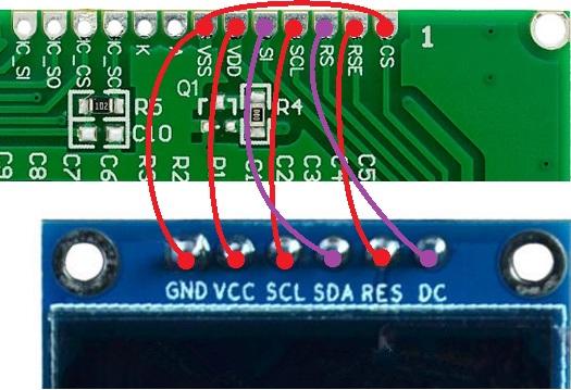
it looks the same. this is what i have thanks
short mmmmm is 120mm short nope and just run out of solder

at lest we know what was going on i think David is right noise looks like shit on the scope
I also ordered two of these displays for myself (from another seller). But long delivery. Promise in a month (or later).
shame no one has this screen so we could do some more testing aswell
shops are shut now will grab some solder tomorrow and use small jumpers and see what we get

ok just found a scrap of solder now jumpers are 20mm long but still no joy.
off for a nap then i will get the scope back out

Don't blame the display yet, a single command can screw everything up, so initializing these things usually require several tries.
Found the cmds in u8g2 to be completely different...
Also lowered the SPI speeds to 140KHz, should work much easier with longer wires, the display will be pretty slow, but this is testing stage!
Edit: v0.2 removed.
just flashed 0.2 still blank and jumpers are 20 mm now thank you for all of your time
update dc=high ,rst=high ,sda and scl are wave forms will have more of a look when i have had a nap
Make connectivity tests with the DMM, testing point-to-point connectivity and isolation between lines.
If good, I don't think it's really the connection, also the pin code had no change, just the commands init commands.
Addressing is the same, I missread the datasheet, was using the wrong cmd!
now flashing
lcd blank must be a problem my end.
i am shore i just see a flicker or i am going mad. and the bad thing is i only see its one time 3 lines
it looks the same. this is what i have thanks
In that picture the power is connected backwards. VDD to GND

! Should go to 3.3V!
Maybe you had a little stroke while drawing? I hope so, otherwise the module might have gone kaput

Also the LED is reversed, A(Anode) should take the positive, and K(Cathode) should go to the negative.
At least, you won't kill the backlight. If you don't see any light coming out, reverse -only- the led connection.
I think it was related to how the commands were sent.This controller might be a little more picky, not sure.
More testing!
Dave you done it there is a faint image on v0.3

just looks like contrast is very low or very high and the text/image was flipped left to right

top to bottom is good

i think i need sleep
Did you miss v0.4.1 I posted earlier?
Added a higher contrast build, too.
yep i missed it just flashed .4.1 and contrast 80 and don't seem to get any screen
just flashed .3 back and image but fliped
i can try agen with .4.1 in the morning but didnt have any image and flashed .3 faint fliped image
I think I finally caught the issue, turn on/off commands were wrong, so that's why you probably had that blink.
Also added additional power-on steps, I think this time will work! (Still might look reversed or flipped).
lets get flash

just very quickly span through new .5 still blank but could be something my end will keep checking
.3 test
https://youtu.be/s9Zx6hZTxqU
Keep comparing it with 0.3 before breaking your head.
I cleaned and reworked the display code, it was prety messy and redudant, now is a lot easier to modify, so you might want to try different initializations sequences.
- Setup the IDE (Easy step, just download and install)
- Download the code in .zip rom github, unpack somewhere
- Run _KSGER_v3.bat to load the profile.
- Open the IDE, import the project at the root of the folder (ignore those inside "board" folder)
- Go to Drivers/graphics/lcd.h
Adjust the first lines as this:
/*    Display selection    */
#define ST7565
//#define SSD1306
Above those lines you can find the command codes.
- The initialization sequences are at start of Drivers/graphics/lcd.c
// CMD_SIZE, DELAY_MS, CMD_DATA
const uint8_t disp_init[] = { // Initialization for ST7565R
    1, 0,   c_disp_off,
    1, 0,   c_bias_7,
    1, 0,   c_adc_norm,
    1, 0,   c_com_norm,
    1, 0,   c_start_line,
    1, 50,  c_pwr_ctrl | c_pwr_boost,
    1, 50,  c_pwr_ctrl | c_pwr_boost | c_pwr_vreg,
    1, 50,  c_pwr_ctrl | c_pwr_boost | c_pwr_follow,
    2, 50,  c_boost_ratio, c_boost_234,
    1, 50,  c_res_ratio | 0x07,
    2, 0,   c_set_volume, 0x16,
    1, 0,   c_disp_off,
    1, 0,   c_all_on
};
Follow the project Readme in Github for more details.
I have the same board as in the picture. Trying to connect on st-link. Already tried with and without rst, with external power and check st-link on different stm without any problem. I just cant connect to this board
@AUTOMOTIVE SOLUTIONS, damn a little more bug. Forgot a small detail about..enabling the final power

That's the slowness caused by not being able to debug the code in real time, waiting for your feedback

islonina, try the manual method, shorting nRST usign tweezers.
Some ST-Link clones have a bug in the PCB design where that signal is connected wrong.
Now i can connect but after chip erase i got error about not accessible elf
@DavidAlfa thank you so much and sorry for the slow testing. i have ordered 2 more lcd's one will be here in 3 days would you like a free screen?
i have tested all. 0.3 is the only one so far with a output. have you seen the vid i posted will look so good. thank you so much what you do for the eevblog i take my hat off.
Ksger_v3_ST7565R_LCD_v0.6d.bin is the best image starts nice but all 0.6 fade away after 3 seconds ish.
i will install ide and keep on trying
Now i can connect but after chip erase i got error about not accessible elf
Please follow the
Instructions.
Ksger_v3_ST7565R_LCD_v0.6d.bin is the best image starts nice but all 0.6 fade away after 3 seconds ish.
Well, that's something! Please attach some videos/pictures!
Now i can connect but after chip erase i got error about not accessible elf
Please follow the Instructions.
I done this on 2 diffrent board already but never got elf error. I already disabled read protection, now i have empty stm32 with only FFF read on all blocks. On github wiki there is no information about this problem