-
the more i think about this, the more complex it gets :-)
Yes.
Another option is to hold/repeat the last value for a couple of samples, this will not affect the logging. -
super, but make it possible to "know" if data fetch from each unit is not answering ALL times in first go ?
like a total retry counter ? we can access some how ?
this way we can fix the issue, new cables, new router, new equipment -
Hi @HKJ, you've clearly done a great job supporting such a wide range of hardware!
It is not me alone, I got a lot of help from people here (You can see a list on the About page).Is the project on github? Sorry if its in the thread somewhere.
No.
I presume that means it isn't open source licenced. You'd get a lot more help from others if it was Open Source rather the proprietary. For instance, what happens if you become too busy with other things in your life to support it, or if it becomes really popular the amount of support, bug fixing etc will become too much of a burden?
Sigrok says it has cross platform build, still, it looks a bit rough at the edges and has plenty of nasty use of macros in the code (just took a quick look), I guess to make it cross platform.Also, I was wondering why you didn't build upon Sigrok, say a new UI and/or adding drivers for missing hardware?
I wanted the program simple to install and use. The program is in Java and works on multiple platforms with one executable file, you could not do that with Sigrok.
What I meant was making it a server, say running Apache and communicating over http and having the UI/front end on another device. Perhaps easier to do so with the Java codebase than C, if it was open sourced!I was hoping to find remote control/logging in a client-server design: backend interfacing with the h/w, say on a R-Pi (which could even be built into test equipment) and the client web / mobile...
I may at some time in the future make it possible to use remote serial ports.
If you want to design your own test equipment, there is documentation on how to interface it to TestController. -
Hi,
maybe a bold question, but would it be possible to add a Manson HCS-3300? I've already found some protocol info on: https://sigrok.org/wiki/Manson_HCS-3xxx_series
-
maybe a bold question, but would it be possible to add a Manson HCS-3300? I've already found some protocol info on: https://sigrok.org/wiki/Manson_HCS-3xxx_series
Anybody with a bit of time can add that supply using a ascii driver.
Documentation: https://lygte-info.dk/project/TestControllerConfigDevice2%20UK.html#Non-SCPI_ascii_devices_(Ascii) -
I presume that means it isn't open source licenced. You'd get a lot more help from others if it was Open Source rather the proprietary. For instance, what happens if you become too busy with other things in your life to support it, or if it becomes really popular the amount of support, bug fixing etc will become too much of a burden?
I do generally maintain my software for a long time and even if I stop maintaining it, it will still continue to work.Sigrok says it has cross platform build, still, it looks a bit rough at the edges and has plenty of nasty use of macros in the code (just took a quick look), I guess to make it cross platform.
I believe Sigrok is compiled to machine code, i.e. it would require more than 10 versions of it to support the same amount of hardware and OS, I support with a single file.
To get TC working you only have to install Java and then run the TC file. To really use Sigrok you basically need to be a programmer, in TC you can make scripts, but you do not need to and can use all the functions without. -
maybe a bold question, but would it be possible to add a Manson HCS-3300? I've already found some protocol info on: https://sigrok.org/wiki/Manson_HCS-3xxx_series
Anybody with a bit of time can add that supply using a ascii driver.
Documentation: https://lygte-info.dk/project/TestControllerConfigDevice2%20UK.html#Non-SCPI_ascii_devices_(Ascii)
Ok, I just had a look into that, but I need more info on the subject to be able to implement this. I've looked at the Ascii Skeleton and a lot of questions. For example, I know the results of a GETD command (VVVVCCCCS\rOK\r) are in mV and mA. There is a definition value Voltage V ... which could handle this, but what does D0..D6 mean?
Is this is a lab benchpower with only very few settings and readings this should be not that difficult to setup, but I can't figure out where to start as in the other drivers there are lots of terms and variables I can't figure out where to find the definition. -
Ok, I just had a look into that, but I need more info on the subject to be able to implement this. I've looked at the Ascii Skeleton and a lot of questions. For example, I know the results of a GETD command (VVVVCCCCS\rOK\r) are in mV and mA. There is a definition value Voltage V ... which could handle this, but what does D0..D6 mean?
D0..D6 is 0 to 6 decimal places when showing the value, you will usually use the number that match the display on the device.
To adjust the input values you usually uses a :readmath: function. It is called #askValuesMathFormat for #askValues, but :readmath: nearly everywhere else.
You may also want to look at the SCPI configuration page, it contains a lot of common stuff for all configuration files: https://lygte-info.dk/project/TestControllerConfigDevice%20UK.html
The general idea is to get a connection to the device, then you can try/test commands from the command line.
-
I do generally maintain my software for a long time and even if I stop maintaining it, it will still continue to work.
Could you cut it in two, and have the device files in git?
Most additions are about that. -
Could you cut it in two, and have the device files in git?
Most additions are about that.
You already have the source code for the device files and I generally update the release files when a new device file is posted here (Except if it is described as test, partial or something like that). -
Hi,
thank you for your time sofar... I hope I'm not bothering you too much with my questions.Ok, I just had a look into that, but I need more info on the subject to be able to implement this. I've looked at the Ascii Skeleton and a lot of questions. For example, I know the results of a GETD command (VVVVCCCCS\rOK\r) are in mV and mA. There is a definition value Voltage V ... which could handle this, but what does D0..D6 mean?
D0..D6 is 0 to 6 decimal places when showing the value, you will usually use the number that match the display on the device.
To adjust the input values you usually uses a :readmath: function. It is called #askValuesMathFormat for #askValues, but :readmath: nearly everywhere else.
You may also want to look at the SCPI configuration page, it contains a lot of common stuff for all configuration files: https://lygte-info.dk/project/TestControllerConfigDevice%20UK.html
The general idea is to get a connection to the device, then you can try/test commands from the command line.
I'm starting to grasp a vague idea... One practical question. With one ASCII command I get the complete status in one string with numbers. First 4 are V, then 4 for A and then a 0 or 1 for CC or CV.. How would I split this into the different values?
To me it looks you need to use askValues to configure which values to get en use scpiCmd to define how to get those values. But in this case I only need one command to get all the values in one go -
I'm starting to grasp a vague idea... One practical question. With one ASCII command I get the complete status in one string with numbers. First 4 are V, then 4 for A and then a 0 or 1 for CC or CV.. How would I split this into the different values?
You use string functions to split it into 3 values with a space between each:
https://lygte-info.dk/project/TestControllerFunctions%20UK.html#String_functions
You may also need to use string function to add a . to the values, if the values is in anything but basic units.To me it looks you need to use askValues to configure which values to get en use scpiCmd to define how to get those values. But in this case I only need one command to get all the values in one go
Generally you place all the tx/rx commands in scpiCmds and then you use the commands you have defined there in the rest of the definition.
You will also want to add commands to set voltage, current, on/off. Adding interface function can be useful for automatic testing. -
Hi all,
I have an Amprobe TMD-56 Thermocouple digital thermometer I really would want to make to work with TestController.
https://www.amprobe.com/product/tmd-56/
Its same meter, and same interface as Omega HH806
https://www.omega.com/en-us/temperature-measurement/temperature-and-humidity-data-loggers/p/HH806
So similar so when asking the Amprobe over serial what ID it have it responds HH806...
Specifications on communication as follows:
Connect over serial with 19200 bps, 8 bit, 1 stopbit, even parity and no flow control.
Send HEX #0A0000NA2 to meter.
The meter then responds. For this response:
Take Byte 5 and 6 as an 16 bit integer and divide by 10 to get temperature of probe 1
Take Byte 10 and 11 as an 16 bit integer and divide by 10 to get temperature of probe 2.
I have been trying lots of things but can not get it to work.
Any of you wise testcontrol stars out there who could help to make, or even come with suggestions on how to make the device file?
More info on communication protocol here:
https://forums.ni.com/ni/attachments/ni/170/1037288/1/8xxprotocol.doc
-
Any of you wise testcontrol stars out there who could help to make, or even come with suggestions on how to make the device file?
It need a specially coded protocol to work fully, but just reading the values looks to be possible:
Use Ascii protocol with #scpiCmds
To read the data you can use the txrxnBin? command
And then a :readmath: with two binConv() function to extract the bits.
You need to return the two values as number with one space between (Like "12.3 45.7").
Something like this:
#scpiCmd values? txrxnBin? 13 #0A0000NA2
:readmath: (binConv(value,5,2)/10.0)+" "+(binConv(value,10,2)/10.0)
-
Is it possible that this program doesn't work with the Brymen BM869S in 500k mode?
I can get it to read and log in 50k mode fine, and about 5 times per second, so according to the screen refresh, but when I switch the meter in 500k mode the readings are very slow, irratic (and if logged, in 50k mode) and it also won't reconnect in 500k mode. -
Is it possible that this program doesn't work with the Brymen BM869S in 500k mode?
I can get it to read and log in 50k mode fine, and about 5 times per second, so according to the screen refresh, but when I switch the meter in 500k mode the readings are very slow, irratic (and if logged, in 50k mode) and it also won't reconnect in 500k mode.
I do not remember if I checked/implemented the 500k mode, but I will check it and fix it (if necessary) soon. -
V2.03 is up
This is mostly additions to TestController, but a few new devices has also been added.
Fixed: Brymen BM869s 500000 count mode.
Added: On Load devices page the right click menu got a option to open web documents used for devices.
Added: FFT View, used to analyse the table data for frequencies
Modified: Popups menu, moved all device function to a submenu (The menu was getting too large)
Added: #helpurl support a DEVICEIP tag that will be replace with actual device ip address if it exist
Added: Keysight DS0X2012A, Keysight DS0X2014A, Keysight DS0X2214A (Thanks bicycleguy)
Changed: jSerialComm updated to V2.90, this includes support for Windows/Mac ARM processors
Added: Center/span input for min/max on "Scales for charts", click on header to switch
Added: #resetDelay for definitions (Maybe needed for some Arduinos)
Added: resetDelay command line option (Maybe needed for some Arduinos)
The serial library has been updated, this included some significant internal changes to the library according to the author. I hope none of this will affect TC.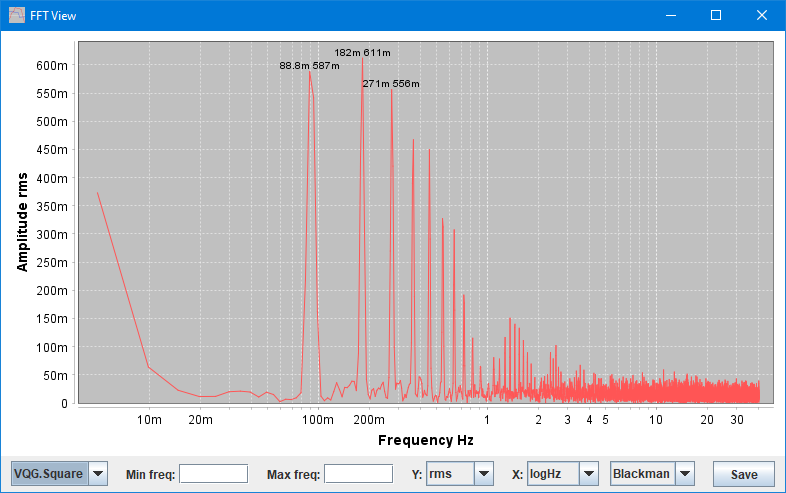
The main addition is a FFT view -
THANKS ALOT much apriciated,
we all see how much work and time you put into this free software,
I plan to push for using it at work,
and at the same time looking for a donate / paypal info ?
how about you add a little about, donate-ware info, so if people feel this help their work, save time, add value to their work,
they can express their gratitude by paying a few $ your way
I cant find any such menu in the program ? -
I plan to push for using it at work,
and at the same time looking for a donate / paypal info ?
how about you add a little about, donate-ware info, so if people feel this help their work, save time, add value to their work,
they can express their gratitude by paying a few $ your way
I cant find any such menu in the program ?
I hope it can be useful at your work.
The email above the download link can be used for donations.
-
HKJ,
TC just keeps getting better
Questions about the #fftView command:
1. I first tried #fftView 3 for the third column and the the console complains "failed due to null" but the window pops up anyway. I (now) get that the argument should be the table column name, but since the fft window actually pops up it is confusing to have the error say "failed". I then tried just #fftView with no arguments and the console gives no error message and the window does not pop up. I would think there should be a console error if the window does not pop up. For me it would be more convenient if it did pop up and then I could manipulate it manually to get what I want.
2. How does this fft work? Normally fft code assumes a constant sampling period. But TC sampling period varies. So, does the fft assume constant sample period at the log interval set point?
3. What would the fft do if the logging starts at one log interval and then TC adjusts the log interval slower due to slow responses? In other words what doe this fft do with a Table record with two or more different set points for the log interval?
4. Is there a limit to the number of points in the Table that the fft can be taken for? Related question, does this FFT always use all the points or is it an fft that always truncates the data to the first 2^n points for a binary number of sample points?
4. I suggest adding a button on the Chart view to open the fftView. It is a little awkward to have to go to the console and type in #fftView + arguments. Great for scripts, not so much for user actively working on the data.
Again, great stuff! -
1. I first tried #fftView 3 for the third column and the the console complains "failed due to null" but the window pops up anyway. I (now) get that the argument should be the table column name, but since the fft window actually pops up it is confusing to have the error say "failed". I then tried just #fftView with no arguments and the console gives no error message and the window does not pop up. I would think there should be a console error if the window does not pop up. For me it would be more convenient if it did pop up and then I could manipulate it manually to get what I want.
Generally you start FFTView from the "Popups" menu, starting it with the #FFTView command is only for scripting (There is some help in the help window).2. How does this fft work? Normally fft code assumes a constant sampling period. But TC sampling period varies. So, does the fft assume constant sample period at the log interval set point?
It assumes constant sample period based on the "time" column, it takes the first and last time stamp and divides by number of samples.3. What would the fft do if the logging starts at one log interval and then TC adjusts the log interval slower due to slow responses? In other words what doe this fft do with a Table record with two or more different set points for the log interval?
It gives wrong results. I was thinking about resampling the data to a constant interval, but I have not done that for now.4. Is there a limit to the number of points in the Table that the fft can be taken for? Related question, does this FFT always use all the points or is it an fft that always truncates the data to the first 2^n points for a binary number of sample points?
The FFT will handle up to half a million points, when there is more it will resample.
On a slow computer it may resample at lower number of samples.
When the number of points to not fit a power of two TC will resamples.4. I suggest adding a button on the Chart view to open the fftView. It is a little awkward to have to go to the console and type in #fftView + arguments. Great for scripts, not so much for user actively working on the data.
I was thinking about where to place the access, in the end I decided to put it with all the other Popups -
Generally you place all the tx/rx commands in scpiCmds and then you use the commands you have defined there in the rest of the definition.
You will also want to add commands to set voltage, current, on/off. Adding interface function can be useful for automatic testing.
I've got a very rudimentary driver and have a few follow-up questions:
1. The device responses with 2 lines first line contains the data (almost always numbers) then a <cr> then "OK". At the moment i use txrx? which seems to ignore the second line, but I'm not sure that's the correct way.
2. On/Off is reversed on the device 0=on 1=off. This works for the buttons on the 'Setup' page, but the red square does not work anymore.
3. Is it possible to calculate for example the Ah and/or Wh in the driver ander report that as Current Values as the device doesn't report those by itself.
-
1. The device responses with 2 lines first line contains the data (almost always numbers) then a <cr> then "OK". At the moment i use txrx? which seems to ignore the second line, but I'm not sure that's the correct way.
Use txrx2? instead2. On/Off is reversed on the device 0=on 1=off. This works for the buttons on the 'Setup' page, but the red square does not work anymore.
Use
:readmath: value==0
to flip the answer.3. Is it possible to calculate for example the Ah and/or Wh in the driver ander report that as Current Values as the device doesn't report those by itself.
No, you cannot add extra columns in the driver, but using the "Math" tab it is easy to do
-
I tried that, but how to get rid of the <cr>OK ?1. The device responses with 2 lines first line contains the data (almost always numbers) then a <cr> then "OK". At the moment i use txrx? which seems to ignore the second line, but I'm not sure that's the correct way.
Use txrx2? instead -
I tried that, but how to get rid of the <cr>OK ?1. The device responses with 2 lines first line contains the data (almost always numbers) then a <cr> then "OK". At the moment i use txrx? which seems to ignore the second line, but I'm not sure that's the correct way.
Use txrx2? instead
There are a lot of functions to edit the answer, see https://lygte-info.dk/project/TestControllerFunctions%20UK.html#String_functions they are used after a :readmath: tag.