-
Hello again!
It seems to work now, thanks! I modded the already existing file and added a changelog. Continuity is now an option too (strangely the meter returns values in volts rather than ohms).
Best wishes!
Replace these two lines:
#value VoltageDC V D4 VDC, VACDC, DIODE
#value Resistance OHMS si OHMS, CONT
and report back.
-
Found a bit of annoyance.
In the window "Scales for chart" and in "Maximum", the entered value there is only visibly retained provided 8 digits after the decimal point is not exceeded.
When entering more than 8 digits after the decimal point "0" is always displayed. But even so, an entered value having 11 digits after the decimal, for example, is honoured in the "Chart" window.
This came to light when measuring small capacitances of around 4 pF. Here "Auto" scaling does not work, so that the maximum chart value needs to be entered manually. 11 digits after the decimal points are needed in my case (UT622E) to display the 1 to 10 pF range, for example.
Multiplying such a small value - 4 pF - by 1000, for example, won't work.
Averaging will obviously not work too. But the graph can be readied to show averaged values in the pF range.
-
Hello again!
These changes do not work, still reporting in "voltages". Even in the manual (and on the display) the value is reported in "voltage" rather than "ohms". So i guess it works as intended, just some oddity with this meter.
-
Does anyone have a Fluke 45 working properly with TestController? I'm trying to connect one now and not having any luck.
I set the meter for 9600 N 8 1 and connected to a terminal program and in response to *IDN? I get "Fluke, 45, (and them more stuff)". When I try to load it in TestController, I get the response that there isn't a match to ID Fluke, 45, . The response I get is exactly as specified in the ID string in the configuration file supplied, written by author Bad Drive in Nov 2020.
Any clues appreciated.
Edit: Got it! In case anyone else has this issue I'll leave the post. The issue was that you have to set the meter configuration to Echo = OFF.
-
With the 34401A attached via RS232, starting TC normally and opening the setup causes an ERROR 101 on the Agilent and the setup dialog box to remain unfilled.
However, starting TC via debug mode and opening the setup causes no error and the dialog box to be filled successfully.
Could this behavior be timing related?
This is currently on Windows 7 32-bit using a full-handshake serial cable as I wanted to exclude any causes by serial handshake errors.
-
Found a bit of annoyance.
In the window "Scales for chart" and in "Maximum", the entered value there is only visibly retained provided 8 digits after the decimal point is not exceeded.
When entering more than 8 digits after the decimal point "0" is always displayed. But even so, an entered value having 11 digits after the decimal, for example, is honoured in the "Chart" window.
This came to light when measuring small capacitances of around 4 pF. Here "Auto" scaling does not work, so that the maximum chart value needs to be entered manually. 11 digits after the decimal points are needed in my case (UT622E) to display the 1 to 10 pF range, for example.
Multiplying such a small value - 4 pF - by 1000, for example, won't work.
Averaging will obviously not work too. But the graph can be readied to show averaged values in the pF range.
I have been thinking about it, I may consider lowering the clamp level a bit. It is used to avoid near zero values where a null is supposed to show.
-
Does anyone have a Fluke 45 working properly with TestController? I'm trying to connect one now and not having any luck.
I set the meter for 9600 N 8 1 and connected to a terminal program and in response to *IDN? I get "Fluke, 45, (and them more stuff)". When I try to load it in TestController, I get the response that there isn't a match to ID Fluke, 45, . The response I get is exactly as specified in the ID string in the configuration file supplied, written by author Bad Drive in Nov 2020.
Any clues appreciated.
Edit: Got it! In case anyone else has this issue I'll leave the post. The issue was that you have to set the meter configuration to Echo = OFF.
To hopefully avoid this in the future I have added a note to the Fluke 45 definition saying echo must be off.
-
With the 34401A attached via RS232, starting TC normally and opening the setup causes an ERROR 101 on the Agilent and the setup dialog box to remain unfilled.
However, starting TC via debug mode and opening the setup causes no error and the dialog box to be filled successfully.
Could this behavior be timing related?
This is currently on Windows 7 32-bit using a full-handshake serial cable as I wanted to exclude any causes by serial handshake errors.
This do sound like a timing problem, I wonder why the handshake do not work. You can add [xx] (where xx is a time in ms) after the commands to probably get around it.
-
Found a bit of annoyance.
In the window "Scales for chart" and in "Maximum", the entered value there is only visibly retained provided 8 digits after the decimal point is not exceeded.
When entering more than 8 digits after the decimal point "0" is always displayed. But even so, an entered value having 11 digits after the decimal, for example, is honoured in the "Chart" window.
This came to light when measuring small capacitances of around 4 pF. Here "Auto" scaling does not work, so that the maximum chart value needs to be entered manually. 11 digits after the decimal points are needed in my case (UT622E) to display the 1 to 10 pF range, for example.
Multiplying such a small value - 4 pF - by 1000, for example, won't work.
Averaging will obviously not work too. But the graph can be readied to show averaged values in the pF range.
I have been thinking about it, I may consider lowering the clamp level a bit. It is used to avoid near zero values where a null is supposed to show.
Maybe leave the default at 8 decimal places. But with the option of say 12 decimal places selectable for a specific case. -
Maybe leave the default at 8 decimal places. But with the option of say 12 decimal places selectable for a specific case.
Another option is to display it as SI values (i.e. with Mkm... etc.) prefix, then you will not get more digits (this depends on actual SI format used https://lygte-info.dk/project/TestControllerConfigDevice%20UK.html#Data_type_definitions, something like SI10p may work nicely), but you will get greater range for low values. -
The 34401A and E3632A are finally working flawless via RS232. I've been troubleshooting various errors for hours until I found out that in the end, two problems were interfering with each other. As these were immanent at two very differently spec'd computers, two OS (Linux and Win7) and with two different cables, I guess others might have the same issues, which is why I include my working device files.
Details regarding the issues found:
1. For communication via RS232, all commands need a delay. For the E3632A, 20ms is needed for a continuously flawless operation. For the 34401A, 10ms seems to work reliable if operated alone or in combination with just one E3632A. If operated together with two E3632A, a reliable continuous readout of values requires 20ms as well. The config files therefore are set to 20ms for both devices. The SAVe and ReCaL procedures on the E3632A require more time, which is why they are set to 200ms. It might be that the time can be shortened further, but 100ms did not work out and as I do not regard that procedure time-critical, I just played save and left it at 200ms that worked.
2. Some commands defined in the device files are transmitted with a trailing value. In cases where these commands are defined as single commands (i.e. without a second command in direct sequence), the definition contains just the command without any further trailing addition. In cases of a definition that contains two commands in one single sequence in which at least the first requires a value to be inserted, there is a placeholder in-between for the position of the value within the sequence. The placeholder is called "(value)". If one now adds a delay in form of [20] to a single command, is necessary to insert the "(value)" placeholder after the command before finishing it with "," and adding the delay [20] afterwards. Otherwise, TC will transmit the command without a value and then transmit the delay as a second sequence via RS232, leading to errors on the device.
Example for case No. 2:Original:
Does not work:
Right way:":write: OUTP"
":write: OUTP;[20]"
":write: OUTP (value);[20]"
One should be aware that the debug mode slows the operation of TC down so that seemingly working delay timings found while testing them in debug mode can cause errors in non-debug mode.
Best wishes,
Christian
-
Not to cause a mix-up with my previous post, here are the same files but with the added functionality to be able to switch the display off and on again on the 34401A and the E3632A.
Long life the VFD!
-
The 34401A and E3632A are finally working flawless via RS232.
I will replace the definitions with your updated version in the next release, thanks.2. Some commands defined in the device files are transmitted with a trailing value. In cases where these commands are defined as single commands (i.e. without a second command in direct sequence), the definition contains just the command without any further trailing addition. In cases of a definition that contains two commands in one single sequence in which at least the first requires a value to be inserted, there is a placeholder in-between for the position of the value within the sequence. The placeholder is called "(value)". If one now adds a delay in form of [20] to a single command, is necessary to insert the "(value)" placeholder after the command before finishing it with "," and adding the delay [20] afterwards. Otherwise, TC will transmit the command without a value and then transmit the delay as a second sequence via RS232, leading to errors on the device.
Example for case No. 2:Original:
Does not work:
Right way:":write: OUTP"
":write: OUTP;[20]"
":write: OUTP (value);[20]"
You are correct in this. The full line is processed for adding the value, later in the process the line is split on ; and each item is transmitted, except for a few virtual commands (Like [20])
Also note that not all drivers work the same way.One should be aware that the debug mode slows the operation of TC down so that seemingly working delay timings found while testing them in debug mode can cause errors in non-debug mode.
It does, even though I have tried to minimize it.
-
Made some modifications in my Powersupply-Test and Battery-Test scripts.
No spectaculair changes, but added some checks.
Removed some small faillures.
Changed information in command window after finishing tests.
-
Hello,
i found an error in the RND KEL103v2 definition.
When i tried to use the Battery Mode, TestController did not update the values, because a part of the parameters was missing in the UDP transmission.
I fixed it and the battery settings are working flawlessly now.
-
PowerSupply Test script with making BurnIn test after testing Voltage and Current depedence.
Test can be started with an Internal Resistance check.
See the graph.
First Internal resistance check.
Then Voltage - Current test.
Then BurnIn test.
In Result in Command Window.txt the results in Testcontroller Command Window.
-
Hi HKJ,
Here are three updated definitions.
I added a few math functions to the HP / Agilent 3458A setup menu. (I needed the NULL / offset function):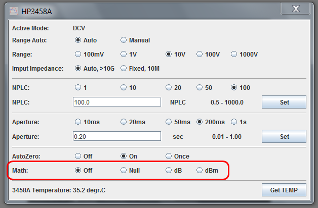
Also I found a small bug in this definition. Checking my other definitions, I also found this small bug in the Racal-Dana counter definitions. So I updated those too.
AgilentHP3458A v1.03: AgilentHP3458A.zip
Racal1991-1992 v1.02: Racal1991-1992.zip
Racal1998-1999 v1.02: Racal1998-1999.zip
Best Regards, Gertjan.
-
Made some modifications in my Powersupply-Test and Battery-Test scripts.
No spectaculair changes, but added some checks.
Removed some small faillures.
Changed information in command window after finishing tests.
The zip file Is updated.i found an error in the RND KEL103v2 definition.
When i tried to use the Battery Mode, TestController did not update the values, because a part of the parameters was missing in the UDP transmission.
I fixed it and the battery settings are working flawlessly now.
This will be included in the next release.PowerSupply Test script with making BurnIn test after testing Voltage and Current depedence.
Test can be started with an Internal Resistance check.
See the graph.
First Internal resistance check.
Then Voltage - Current test.
Then BurnIn test.
In Result in Command Window.txt the results in Testcontroller Command Window.
The website Is updated.Here are three updated definitions.
I added a few math functions to the HP / Agilent 3458A setup menu. (I needed the NULL / offset function):
Also I found a small bug in this definition. Checking my other definitions, I also found this small bug in the Racal-Dana counter definitions. So I updated those too.
All 3 will be update in next release. -
Hi HKJ,
I wrote a device definition file for the Rigol DG1000Z series ARB Generators (DG1022Z, DG1032Z and DG1062Z)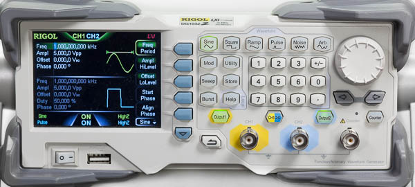
IMG_2391 Rigol DG1032Z crop-2000pix.jpg
This SCPI definition is based on the Rigol DG9xx config file by bateau020. Which in turn was based on the SiglentSDGxxxx definition by HKJ and klausES.
Mostly is was an adaption to the capabilities of the DG1000Z. And work around the SCPI quirks of these ARBs. For instance, querying the (ARB) DC offset does not work. Instead of the offset for DC, the offset for Sine is returned. As a workaround, the DC offset value is now also written to SINe, to get the correct TestController read-out.
The setup Menu for DG100Z: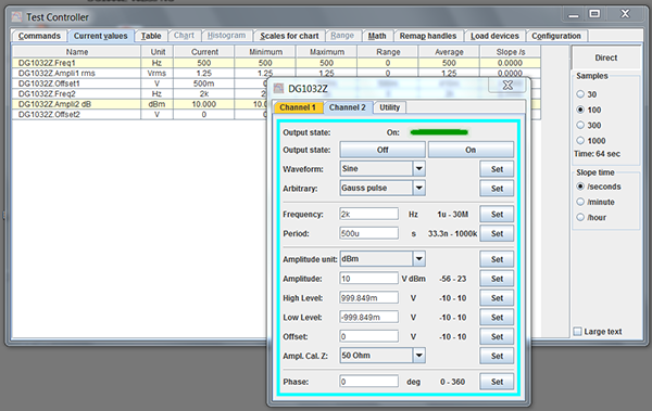
IMG_0043 Rigol DG1000Z screenshot-2000pix.jpg
Please find the definition file here: Rigol_DG1000Z.zip
Regards, Gertjan.
-
I wrote a device definition file for the Rigol DG1000Z series ARB Generators (DG1022Z, DG1032Z and DG1062Z)
They will be included, thanks. -
V2.44 is up
A lot of new/modified definitions and a few fixes to TestController
Changed: Scales for chart uses SI prefix in numbers.
Added: Rigol DG1022Z, Rigol DG1032Z, Rigol DG1062Z arb generator (Thanks Gertjan)
Updated: HP3458A and Racal (Thanks Gertjan)
Changed: HP34401A & E363xA bench meter updated (Thanks the Chris)
Added: Array 372zA electronic load (Thanks Finnaaah)
Added: UNI-T UT325 Tenma 72-7715 thermometer (Requires hardware modifications to device).
Added: Hioki DM7275, Hioki DM7276 Precision DC Voltmeter (Thanks Lajt)
Added: isLogging(), isLoggingToDisk(), loggingInterval() functions.
Added: Riden DPS5020 power supply (Thanks Mayco)
Fixed: Riden 60xx, itow not working (Thanks Pukker)
Fixed: AR488Lan GPIB interface was not selectable
Fixed: ProLogic GPIB uses lowercase control clr/llo/loc/trg commands
Changed: Block driver Ascii input will ignore any non-numeric character except -
Added: Block driver special minus tag
Added: Block driver support for end termination
Added: Fluke 8840A Digital Multimeter (Thanks Gertjan)
Added: Rigol MSO5104 Oscillioscope (Thanks Gulftown)
Added: Socket support for Definition driver in DMM2
Added: Support for GPIB control lines in SCPIx driver
-
Hi HKJ,
Congrats with the new version. But is there room in V2.44 for one more definition?
This is a definition for the Keithley K199 System DMM.
This oldie but Goldie is still popular and rightly so. It is fast and stable. The big red alphanumeric LED display is a pleasure to use, and readable from a long distance.
It's non-heated reference makes the meter usable right after switching on. (although the draw back is of course a slightly worse tempco.)
Just like modern Keithley's, it reduces noise by using selectable intelligent filtering, instead of longer NPLC's. So it can be fast, and still have a stable, noise reduced, reading.
Over the GPIB there is an extra digit, that is still stable.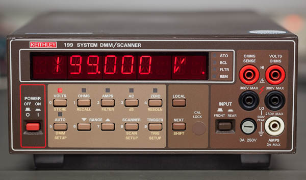
IMG_1852 Keithley 199-2000pix.jpg
A nice feature is "Auto/Cal Multiplex". The Model 199 has built-in multiplex routines that automatically calibrate and zero the instrument, so as to maintain its high accuracy. When enabled this is done before every measurement.
All K199 functions are supported in this definition: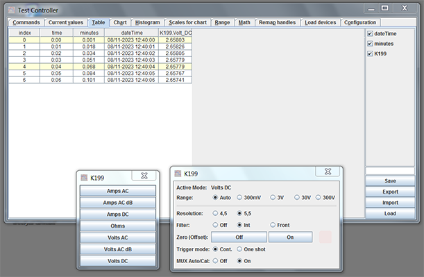
K199 screenshot DCV default settings-1000pix.png
A lot of Keithley 199's are equipped with a scanner card. This definition does not support that scanner card. I tend to just use more DMM's.
Also useful are the AC dB modes. TRMS, with 0dB=1V, or relative. A continuos range from -75dBV to +49dBV, with a resolution of 0,01dB.
And the frequency range is also not too shabby: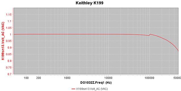
Keithley K199 freq-800x400pix.png
With -1,21dB @ 500kHz, this frequency curve can compete with any modern meter. (-3dB 5Hz...880kHz)
Please find the Keithley K199 definition file here: Keithley199.zip
Best regards, Gertjan.
-
Thanks especially for this:V2.44 is up
Changed: Scales for chart uses SI prefix in numbers.
Extremely useful.
-
Hi,
when using the Rigol DP832 on the LAN interface i regularily got an invalid message and a timeout with numeric settings.
I added :updatedelayed: 0.1 to every command, now its working flawlessly.
I also added the Rigol DP832 without the A suffix.
I attached the updated txt file.
-
thks to HKJ and all the contributors to this software .. kudos

it will become an huge asset to many people