-
Hi Torch
Do you think that it might be related to the fact that my Ultrascope software was fairly recentversion 2.08 I believe and that by downgrading my version fron 02.05 SP2 to 02.02.SP2 the Ultrascope software doesn't work with this version?
Check out my reply in the other rigol thread -
I didn't realize this was asked in two different threads, but Chet T16's post looks like a very good answer.
-
I didn't realize this was asked in two different threads, but Chet T16's post looks like a very good answer.
Three! It has a seperate post of it own too
-
Gee, so there is.
@ flyingfrancisco: At the bottom of the page is a "notify" link. You can use it to have the forum e-mail you a notice when there is a reply to that topic. That way you don't miss any answers to your question and don't need to ask the question in multiple places. -
i prefer "unread post" at the top. i dont just get notified the thread i posted, but any recent activity in any new/old threads. so you wont miss anything of interest (or uninterest too
 ).
).
-
Ok Guys be patient with me, but this dummys guide is a tad long winded and lost me at the point where we are asked to download * download rigupgr.zip from shafri's post here.
I cannot find any file only more & more text!
Anybody found a simpler way, or know where all the darned files are? -
Anybody found a simpler way, or know where all the darned files are?
page #1, post #1, by polossatik.
-
I'm happy to say 2 more version 02.05-SP2 DS1052's patched without a hitch.
I'm running Windows 7 x64 and everything worked fine.
I grabbed the bundle put together by torch on page 47 http://picturehosting.verhey.org/rigol/DS1052Eupgr_tools.zip (thanks torch for sweeping all of the pieces into one easy to use bundle). I used only the files in the bundle and of course the instructions on page 1. It was about a 20 minute process for the first scope since I was checking everything twice and twice again. The second scope was done in less than 10 minutes.
Thanks again to all of you for figuring this out and putting together the tools. -
There couldn't possibly be a simpler way!
Direct link to attachment
Thanks Chet for the link, guess I'll have to read all 49 prev pages first, Ultrascope does not run either with missing dll error, another google required. -
Thanks Chet for the link, guess I'll have to read all 49 prev pages first, Ultrascope does not run either with missing dll error, another google required.
You don't need to read the whole story. You need to read page 1, post 1. All the critical information has been continuously updated in that post through the dedicated efforts of Polossatik.
To make things easier, I put all the files together in one package that you can download from
DS1052 Upgrade tools zip file
EXCEPT Ultrascope (which comes from Rigol)
However, since it is *possible* that the new version of Ultrascope is preventing the scope from connecting when downgraded, here is a version that is known to work with the older firmware:
Ultrascope 1.07 installation files
(there are links to all these on the front page, but some of them are at annoying hosting sites that make you wait unless you pay a premium.) -
Thanks Chet for the link, guess I'll have to read all 49 prev pages first, Ultrascope does not run either with missing dll error, another google required.
You don't need to read the whole story. You need to read page 1, post 1. All the critical information has been continuously updated in that post through the dedicated efforts of Polossatik.
To make things easier, I put all the files together in one package that you can download from
DS1052 Upgrade tools zip file
EXCEPT Ultrascope (which comes from Rigol)
Great stuff torch, have got everything, even Ultrascope now functions ok, cheers mate! -
Great stuff torch, have got everything, even Ultrascope now functions ok, cheers mate!
So Ultrascope v 00.01.7 worked, but v 00.01.08 did not?
That is important information for the next guy. -
I'm running 00.01.07 under Windows 7 x64 and it seems to work fine
-
Solution: increase the pulse duration so it's much longer than the rise time. This ensures that the rising edge is over before the falling edge appears at the input. A charge line can be used to increase this pulse duration
Ok, I added 40" of RG-174/U (couldn't get any RG-178/U), the trim pot and changed the cap to 10pF. I adjusted the trim pot to give as flat a signal across the top as I could. It's certainly wider than the rise time. This is the result (0.34/1.8*1000=188MHz, right?):
-
So rise time actually got faster with a wider pulse, interesting. Don't see an obvious explanation for that, unless there is something weird going on with the pulse shape. This is hard to verify without a faster scope, though.
I am a bit suspicious of the automated rise time measurement. My estimate of 10-to-90 rise time from your screenshot would be around 2.5ns. Does this scope always underestimate rise times? Does it show 20-to-80 rise times? Or is my estimate wrong? Did you try dot display to see if it's undersampled and if interpolation is working properly? -
Yes, looks more like 2.4 - 2.5 ns to me too (start slightly before the 2 ns division and ends 1.2 division after)
-
Unfortunately, he doesn't actually give his measurements in that post that I can see, which may be important since I'm not sure he's using the same stuff.
You'd have to ask him directly.The app note specifies 40" of 50 ohm "hard line or at least teflon-based & rated for HF transmission", but he says he used RG-174/u, which is polyethylene based. (I think "hard line" refers to the thick direct-bury co-ax with the solid shield?) RG-178/u is teflon based though -- maybe it was a typo? Or maybe it's not actually that important?
If it attenuates high frequencies, it might increase the rise time and deteriorate pulse shape. I assume hard line refers to something like semi-rigid coax, which has superior performance compared to normal coax with a braided shield. Janne's result with RG-174 seemed quite satisfactory, though.What is actually more important: will this technique work with the AN47 circuit or does it require the AN94 version? There are some differences I assume the most important is the change in the cap value to 10pf and the addition of the damping resistor? The array of 200 ohm resistors in parallel add up to equal the 50 ohm termination of the AN47, why would he splay them out like that? Spreading the current distribution to minimize RF or something?
I think Janne has used it with (a modified version of) the AN47 circuit, Jim Williams did it with the AN94 version (which also has some other improvements). Paralleled resistors are probably to reduce parasitic inductance, splaying them out will reduce parasitic capacitance, both will screw up the impedance at high frequencies. Hence the short lead length and use of SMD components. -
Oh this is turning into an interesting learning experience
 Here's some experiments and what I think they mean:
First, I switched out the probes. Instead of the supplied Rigol 150MHz probe, I used a 250MHz probe (Coline M12W). I carefully adjusted both matching pots according to the directions. I realize that this is not fair, given that the purpose of this was to test the system supplied by Rigol as a whole, but thought it might make a difference. I also selected "Dots" and turned on persistence. Here is the result: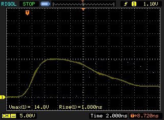
You can see the calculated rise time is just about the same as before. Notice that the line is a touch thick in places -- my circuit is still on the breadboard which I *think* is the cause of the jitter.
But WAIT! If we change the time base to 5ns, something interesting happens: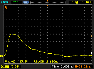
WTF!!!
While in both cases, the leading edge of the pulse is clearly shown, in the 5ns shot, the *trailing* edge has dropped further back to 0. Using the manual cursors, It appears that the Rigol is using the displayed trailing edge when determining the minimum voltage for the rise-time calculation, NOT the displayed leading edge. I don't think this is the right way to do it. Correct me if I'm wrong, but rise time should be looking at the pre-trigger minimum, not the post-trigger minimum, should it not?
With that thought in mind, I used the manual cursors to carefully plot the 10% and 90% points, flipping back and forth between X and Y displays to ensure the points coincided: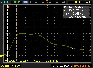
And now, back to the original Rigol 150MHz probe for a manual measurement: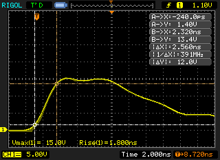
So, allowing for manual error and the fudge factor caused by the jitter in my circuit, I think it's fair to say the rise time is 2.5ns +/- .06ns? Which suggests a Gaussian bandwidth of 3.4\2.5*1000 = 136MHz?
EDIT: Forgot two things: first, thanks to tnt and alm for teaching me not to trust the automatic measurements. And second, this seems to confirm that telling the scope it's now a 150MHz DS1152E-EDU model means bumpkiss. Once the input filter is defeated with the 100MHz mod, that's all you get. Anything more requires a hardware mod, if it's possible at all. -
First, I switched out the probes. Instead of the supplied Rigol 150MHz probe, I used a 250MHz probe (Coline M12W). I carefully adjusted both matching pots according to the directions. I realize that this is not fair, given that the purpose of this was to test the system supplied by Rigol as a whole, but thought it might make a difference.
I think testing just the scope is fair. In the end, the usable bandwidth will be determined by both the probe and the scope, but for the purpose of evaluating the bandwidth of the scope, I would ignore the probe. Ideally I would directly connect the pulser to the input with a feed-through terminator in between, I think this is how Jim Williams did it. Testing probes is also useful, but basically a separate issue.I also selected "Dots" and turned on persistence. Here is the result:
So no issue with interpolation or sampling. My initial thought was that the automated measurement maybe used the uninterpolated signal, and someone has shown that the sin x/x interpolation is not perfect.You can see the calculated rise time is just about the same as before. Notice that the line is a touch thick in places -- my circuit is still on the breadboard which I *think* is the cause of the jitter.
I hope that's not a solderless breadboard, I would build a circuit like this on a piece of copperclad if I didn't have a proper PCB. Any parasitics may severely impact the performance. Something like a solderless breadboard would have parasitics one or two orders of magnitude worse than the parallel termination resistors Jim Williams is worrying about.While in both cases, the leading edge of the pulse is clearly shown, in the 5ns shot, the *trailing* edge has dropped further back to 0. Using the manual cursors, It appears that the Rigol is using the displayed trailing edge when determining the minimum voltage for the rise-time calculation, NOT the displayed leading edge. I don't think this is the right way to do it. Correct me if I'm wrong, but rise time should be looking at the pre-trigger minimum, not the post-trigger minimum, should it not?
There's definitely something strange about the measurement. Does moving the trigger point to the right at 2ns/div so the low signal is longer help at all? Attached is a section from a Tek DSO manual about how automated measurements determines the min and max. Rigol may be using something similar, I haven't checked their documentation.So, allowing for manual error and the fudge factor caused by the jitter in my circuit, I think it's fair to say the rise time is 2.5ns +/- .06ns? Which suggests a Gaussian bandwidth of 3.4\2.5*1000 = 136MHz?
The usual conversion factor is actually 0.35, not 0.34,, but I don't think it makes much sense to calculate this with many digits of precision, since the scope's response is unlikely to be perfectly Gaussian anyway. I would say that according to these results, the bandwidth is probably around 140MHz at these settings.
Any idea how this compares to your earlier measurements with the semi-Dirac pulse? Do you have a saved screenshot that you can use to estimate the rise time from? I'm wondering how much difference the very short pulse makes in this system.EDIT: Forgot two things: first, thanks to tnt and alm for teaching me not to trust the automatic measurements. And second, this seems to confirm that telling the scope it's now a 150MHz DS1152E-EDU model means bumpkiss. Once the input filter is defeated with the 100MHz mod, that's all you get. Anything more requires a hardware mod, if it's possible at all.
Agreed, it doesn't appear to have 150MHz bandwidth. -
but for the purpose of evaluating the bandwidth of the scope, I would ignore the probe. Ideally I would directly connect the pulser to the input with a feed-through terminator in between, I think this is how Jim Williams did it. Testing probes is also useful, but basically a separate issue.
Yes, that is the plan in the end. I started with the breadboard just to make sure I could get things to work, but I have the hardware to finish this properly. You have to understand the way my luck usually runs: Out of the 2-pack of transistors I bought for this, one was DOA right out of the package. I also bought the wrong IC (well, actually, I special-ordered the right one -- Sayal shipped the -12 version instead). And they only had 2 MUR-120 diodes in stock initially, so I decided to try a slightly slower one until I could get a third.QuoteSo no issue with interpolation or sampling. My initial thought was that the automated measurement maybe used the uninterpolated signal, and someone has shown that the sin x/x interpolation is not perfect.
I should have mentioned that sinx/x was off for all measurements shown. I did play with it a few times and it didn't seem to make any difference though.QuoteI hope that's not a solderless breadboard, I would build a circuit like this on a piece of copperclad if I didn't have a proper PCB. Any parasitics may severely impact the performance. Something like a solderless breadboard would have parasitics one or two orders of magnitude worse than the parallel termination resistors Jim Williams is worrying about.
Ummm, can I plead the fifth on this question? I plan to break out a soldering iron in the near future, I promise! Quote
There's definitely something strange about the measurement. Does moving the trigger point to the right at 2ns/div so the low signal is longer help at all?
Yes, that seems to force it to use the pre-trigger value as the low: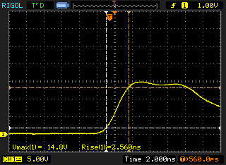 Quote
QuoteThe usual conversion factor is actually 0.35, not 0.34,, but I don't think it makes much sense to calculate this with many digits of precision, since the scope's response is unlikely to be perfectly Gaussian anyway. I would say that according to these results, the bandwidth is probably around 140MHz at these settings.
I've seen both 0.34 and 0.35, so I've been using the 0.34 factor as it produces the least optimistic results.QuoteAny idea how this compares to your earlier measurements with the semi-Dirac pulse? Do you have a saved screenshot that you can use to estimate the rise time from? I'm wondering how much difference the very short pulse makes in this system.
Here's one of the original circuit, but with vectors, Rigol probes, etc.: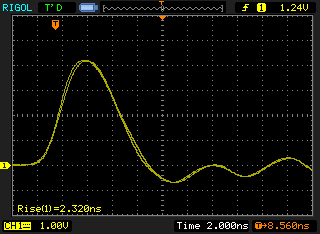
Here's one with the 250MHz probes, dots, persistence, 10pF cap, etc. but with the charge cable disconnected to shorten the pulse back up: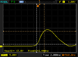
-
Quote
Unfortunately, he doesn't actually give his measurements in that post that I can see, which may be important since I'm not sure he's using the same stuff.
Yes, my version is the AN-47 one, and I just connected the coax in parallel with the collector capacitor, without inductor or adjustable series resistor with capacitor. I think one must be very careful when working with this stuff, it is really easy to pull wrong conclusions, if proper equipment is not available. Verifying the pulse requires a high bandwidth scope (+5 GHz). It seems that RG-178, RG-174 or RG-316 are pretty much the same performance-wise, but 316 and 178 are more robust environmentally. Hard line is probably rigid coax, which means solid copper tube with an insulator dielectric and center conductor.
Here is a picture:
I have some ideas how to improve this. BNC connection seems to be difficult thing to do optimally (at least for my taste), as most PCB connectors seem to have a quite long area of uncontrolled impedance. Soldering components directly to the BNC jack leaves relatively large loops 3D-wise (maybe I'm getting little paranoid here). I think it would be best to begin the 50 ohm transmission line right from the transistor emitter, where the termination resistors are located. Maybe an edge mount SMA connector is the solution:
Regards,
Janne -
I have some ideas how to improve this. BNC connection seems to be difficult thing to do optimally (at least for my taste), as most PCB connectors seem to have a quite long area of uncontrolled impedance. Soldering components directly to the BNC jack leaves relatively large loops 3D-wise (maybe I'm getting little paranoid here). I think it would be best to begin the 50 ohm transmission line right from the transistor emitter, where the termination resistors are located. Maybe an edge mount SMA connector is the solution:
Regards,
Janne
This is how I did it:
https://www.eevblog.com/forum/index.php?topic=30.msg3005#msg3005 -
Jahonen, I have a question for you. The picture of the pulse-generator, seems to me like a factory-made device. Can you tell me where you bought it?
-
Jahonen, I have a question for you. The picture of the pulse-generator, seems to me like a factory-made device. Can you tell me where you bought it?
Actually, only the PCB is factory-made, the rest is hand-assembled
BTW, I think we should create a separate thread considering these pulse generators, to avoid hijacking this Rigol-specific thread.
Regards,
Janne