Did you ever ask yourself why the bar on an electric train's overhead contact system doesn't wear out in a couple of days?
That's actually complicated, and there have been evolving designs for contact materials and other factors to improve performance.
One key element is that the overhead wire sweeps from side to side and does not have a single contact patch on the pantograph.
You, sir, have WAY too much cool gear, and I'm insanely jealous.

Seriously though you've gotta show some of this off in a video. How else can you justify it? :-D
Sent from my iPhone using Tapatalk
Did you ever ask yourself why the bar on an electric train's overhead contact system doesn't wear out in a couple of days?
It's the same reason the rotary switch contact does. 
Electric train's pantograph uses
carbon strips, softer than copper- like in a brushed DC motor commutator. But I see your point about the physics.
Thickness of the PCB copper compared with the wiper metal, I thought around 1/10 and thinner would lose. The wear model says it's hardness and force.
Another factor I notice is switch diameter makes the far outside (ring) path longer so the inner rings (wipers) don't wear as much.
Just looking at it to see why the cheap meters rotary switches did poorly. They have to redesign their wiper, less force it seems.
Actually, since I am horribly bored in the cleanroom waiting for the vacuum press and laser to do their job, I'll disassemble a DT-830 and put the PCB under the profilometer 
That would be an easy test. Let's see what you came up with.
I'm wondering if the problem is in the wipers, not the PCB traces. When the wiper starts to look like this it makes sense (to me) that it will wear out the PCB/traces much faster.
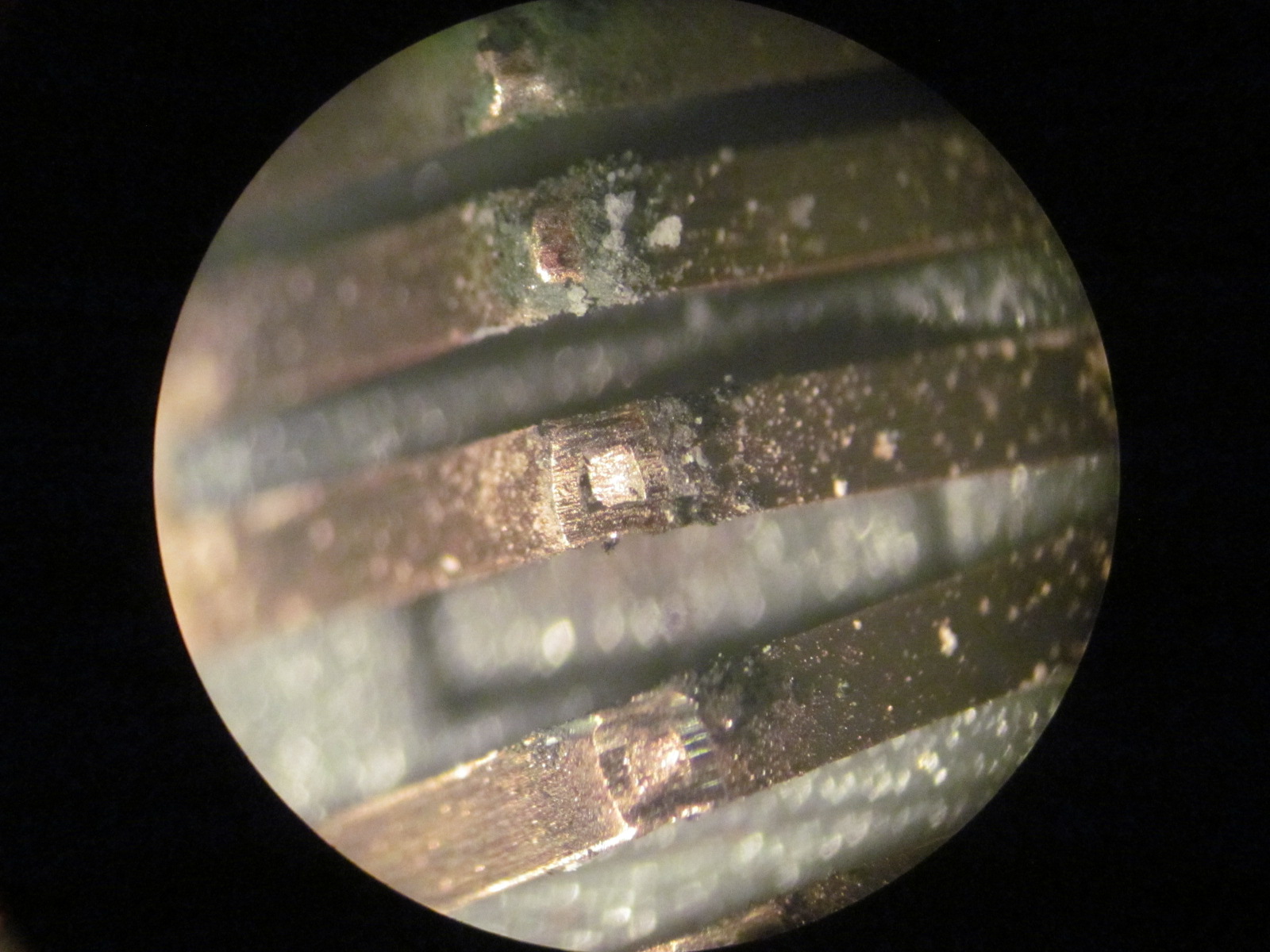
And as noted, the wear on the PCB/traces is spread out over the entire turn of the dial. It's a lot less than the concentrated 100% wear on the wiper.
Electric train's pantograph uses carbon strips, softer than copper
"Pantograph".
That's the word I couldn't remember...
One key element is that the overhead wire sweeps from side to side and does not have a single contact patch on the pantograph.
Spoiler!
I wonder if they could to the same with rotary switch traces on PCBs. It would look pretty if they weaved from side to side.
Actually, since I am horribly bored in the cleanroom waiting for the vacuum press and laser to do their job, I'll disassemble a DT-830 and put the PCB under the profilometer
That would be an easy test. Let's see what you came up with.
Forgot the DT830 at home, but we have a whoooole pile of Uni-T 61Es

The contact pressure (force/area) is probably the thing to look at.
You'd have to estimate the contact (wiper) area and its cantilever spring force. Maybe a phono cartridge tracking force gauge or the drug dealer special (scale) would explain the high wear.
Checked and my AN8008 has all copper wipers, no steel. Not sure if annealed or hardened.
The contact pressure (force/area) is probably the thing to look at.
Right because the obviouse hole in the middle of the pad couldn't have anything to do with it.
Someone was using it for proper work so couldn't exactly kick them of it to do my measurement. But I'll just do it on Thursday then, for now you can pick which DT-830 I should let suffer.

A few side notes: The black one on the left seems to kind of work as intended and has the best build quality. The yellow and crappy blue one have unfinished soldering on the transistor tester, and I had to open up the miniature ANENG to losen the tension on the PCB so I could operate the rotary switch.
The left one is the "upgraded" temperature model. The best version I think (functionality, otherwise the small version looks great, such a small size). I don't have one and can't say about the inside.
the yellow one should suffer, i hate that colour.
it always makes me think of telephone engineers!!
Joe, I just noticed something..
As per the poll atop the thread (and doubled sub's), maybe we're gonna be need a holiday custom BBQ and Fireworks?
I for one would like to see if a lightly smoked Fluke 10 or 12 would ruffle those YouTube button pushers

Wife says no on this one.
But delivered in 15-25 working days!
Wife says no on this one.
But delivered in 15-25 working days!
Too fast, the models in my day took 9 months!
Why would they supply 10 amp leads if it only can do 600ma?

Why would they supply 10 amp leads if it only can do 600ma?
Simple: Because they want the Ohms measurements to be super accurate.
Why would they supply 10 amp leads if it only can do 600ma?
Simple: Because they want the Ohms measurements to be super accurate.
How would printing 10A on the probe help with that? Even probes with fairly thin wires has the 10A stamp on them.
The resistance in probes usual below 0.1ohm each (Down to 0.03ohm for good probes), i.e. it do not have much influence on the ohm range.
The resistance in probes usual below 0.1ohm each (Down to 0.03ohm for good probes), i.e. it do not have much influence on the ohm range.
Not if it was a "600mA" probe.
The resistance in probes usual below 0.1ohm each (Down to 0.03ohm for good probes), i.e. it do not have much influence on the ohm range.
Not if it was a "600mA" probe.
Things hide in plain sight

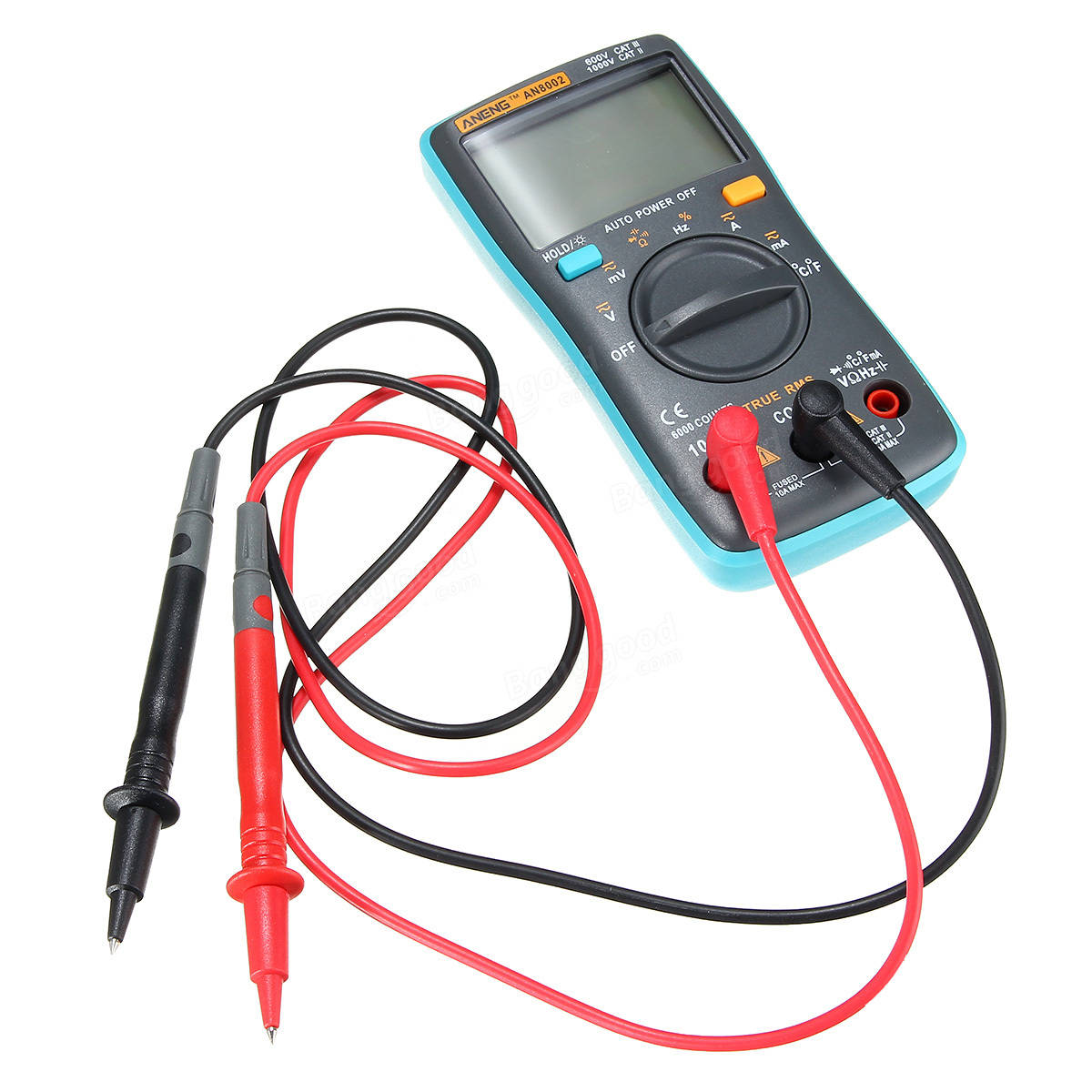
those probes looked familiar (same shorty's that came with my Aneng 8002).
Things hide in plain sight those probes looked familiar (same shorty's that came with my Aneng 8002).
The Aneng probes are about 0.06ohm each.
Things hide in plain sight those probes looked familiar (same shorty's that came with my Aneng 8002).
they arent like the ones that came with mine.
Why would they supply 10 amp leads if it only can do 600ma?
Simple: Because they want the Ohms measurements to be super accurate.
How would printing 10A on the probe help with that? Even probes with fairly thin wires has the 10A stamp on them.
The resistance in probes usual below 0.1ohm each (Down to 0.03ohm for good probes), i.e. it do not have much influence on the ohm range.
This all seems to be true.
Here I am attempting to put 10A through various probes. Note that the two 830s never made it up this high.