I can see the posts now, "I've owned that meter for 10 years and its never had a problem. " 
Yes, I think this is a great exercise but, differently than your rotary test or even the transients, it is much harder to translate a constant vibration pattern to a real world scenario. A constant vibration table seems closer to leaving the meter on top of a car's engine or the washing machine in a cycle spin, but it can barely translate to the G forces subjected by falls, for example.
However, we do what we got to do.
I can see the posts now, "I've owned that meter for 10 years and its never had a problem. "
Yes, I think this is a great exercise but, differently than your rotary test or even the transients, it is much harder to translate a constant vibration pattern to a real world scenario. A constant vibration table seems closer to leaving the meter on top of a car's engine or the washing machine in a cycle spin, but it can barely translate to the G forces subjected by falls, for example.
However, we do what we got to do.
I don't see it being any different than other tests I have ran. I don't try to come up with real world scenarios but rather some standard way that they can be evaluated to compare their performance. I could for example find some obscure circuit that was once use that causes some transient that may damage a meter. If I adopt that as my standard, I can only tell what meters survive it. Not how much more they could take or how close the ones were that failed. The rotary switch life test is similar. I keep track of the contact resistance to get an idea of how the meters perform while they are being cycled. One way would be to take the meter apart during the test and spit shine the contacts to see how they are wearing.
I would like to weed out the better class of meters, just like I have done with every other test. In this case, I could have different profiles. That's a ways out.
I can see the posts now, "I've owned that meter for 10 years and its never had a problem. "
I have a uni-t for 50b for 10 years and had problems like burn 500mA fuses, almost neutralized the Amps shunt while poking UPS outlet ( saved by RCD), original leads are out. Vibration is a good exercice for comparisson between meters whether they keep the measures stable during that kind of stress or some maybe component snaps out of the PCB

But only takes some water to turn years into seconds,
I doubt I would try and power them up during the test and take any readings. While I can believe that with some of the meters, the adjustment pots could move. The bigger problem is that some meters, like the 121GW for example, are sensitive to changing magnetic fields. It's early and I may change my view of this. I can see doing some sort of before and after test for meters along with pulling it apart for inspection.
It will of course be very interesting to see vibration tests on different multimeters and especially Flukes. Because they have removed the "Vibration" and "Shock" heads from the specifications of their multimeters in current revisions. Either they feel no more confident or the requirements have gone more stringent.
From the Fluke 189 manual:
Per MIL-T-PRF 28800 for Class II instruments
Looking at the standard for a Class 2, for the sinusoidal profile they sweep from 5 - 55Hz and 1.5mm down to 0.5mm. This may be doable with the home made table. This document is available for free on-line.
Making the round trip from 5 to 55Hz.
The frequency follows quite well the table attached in the previous post and displacement results "touché" . It is required to do a pause between frequency ranges while testing?
It is required to do a pause between frequency ranges while testing?
Like the transient testing, I am loosely using the standards as a guide. I provided a link to the standard if you would like to read it. I suggest section 4.5.5.3.2. At this time, I plan to run a linear sweep that follows that profile. Maybe run 3 cycles, up and down, half hour per cycle. I have no plans to search for resonance. I'll just let it run and do a before and after functional test and inspection. I am also thinking to just run it in the one axis, backside down, rather than to look at all three. It's all up in the air for now until I actually try running a few meters.
Thanks for the info related to the standard and the go to. Hope the needle of that Multimeter survives
Meanwhile check out the Vbe's supposed aneng basher , Mestek DM91A:
https://youtu.be/XojTrnXq_LUlooks better built and uses more common fuses, ,maybe 5x20mm not tiny .
Thanks for the info related to the standard and the go to. Hope the needle of that Multimeter survives
It was a fairly inexpensive meter and has a bit of weight to it compared with the pocket meter.
I'm not sure which axis would be the worse for this particular meter but I am thinking to run them as shown.
***
Watched his last video. Would have liked to have seen the PCB removed so we could see the switch contacts. I suspect it just uses the single PTC and some transistors for the clamp. Maybe a TVS in there. I doubt it would do very well in my transient testing.
On my bike, I have a mechanical pressure gauge which is filled with glycerine to dampen the pulses and vibrations. Maybe the high end analog meters had some sort of dampeners but this meter doesn't and had a few resonate frequencies. Poor meter....
https://youtu.be/45LaMWZ9en4
So I take it we could never count on this meter at the Baja 1000?
Wow looks like the needle is having a bad day ilke offroad indeed , What about inside ? Any loosy components?
The mechanical meter did not hold up very well. Note the adjustment set to both extremes. One of the batteries had leaked and the vibration caused the solution to spray all over inside the meter. What a mess...
Looks like you have discovered a new technique for accelerated battery ageing testing.
This reminds me of the first meter I blew up. A Micronta 212. I might buy one off ebay if I see one cheap to see if I can recreate that moment on video. The entire meter front filled up with smoke and the needle fell off after leaving it on the 15V DC range and poking a 300V AC HT secondary on a valve radio transformer.
This reminds me of the first meter I blew up. A Micronta 212. I might buy one off ebay if I see one cheap to see if I can recreate that moment on video. The entire meter front filled up with smoke and the needle fell off after leaving it on the 15V DC range and poking a 300V AC HT secondary on a valve radio transformer.
This could be the victim..
 https://www.ebay.co.uk/itm/Radio-Shack-Micronta-22-212-multimeter-works/123706889646
I think I'd probably put 10GBP to it. That is coming up at 28 GBP. Some idiot is selling one here for 49.99 GBP as well which is a joke! It's that bad at 2k/volt it's worth nothing!
So the 1.1M was replaced with a short... What could go wrong??!! lol.
I remember changing burned resistors on my old analog meter using parts I scavenged from old radios and TV sets.

I still have a similar model called protek a800, analog meter, but it is a pocket meter.
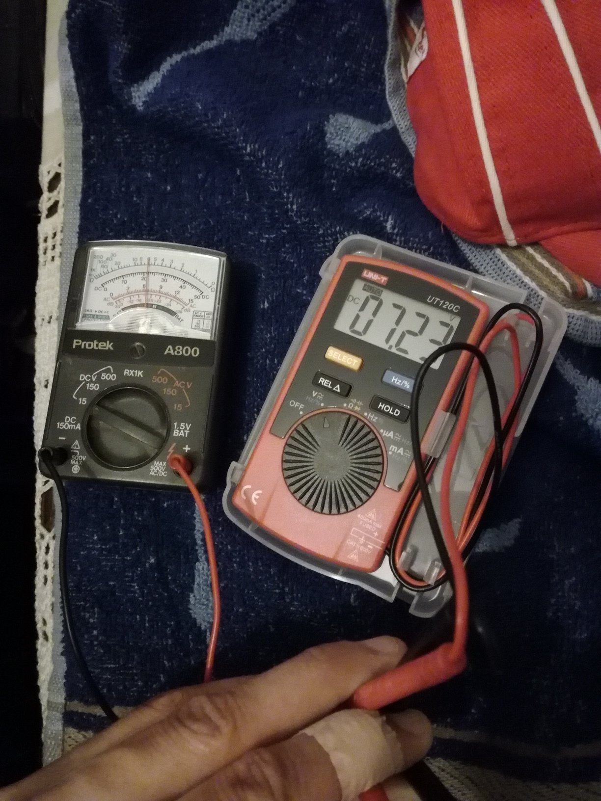
The battery left inside leaked a bit but didn't take much damaged on the spring contacs.