An anagram of Batteriser is "I err at best"
I think there might be a faint date printed on the metal frame (bottom right). KS2015 or 2016?

Can some one please go in and check if there is a DATE, MONTH, YEAR embeded in the original picturefile, properties, on the page where the screen capture is from, the date that they are taken... That would tell us a lot!
First thing I checked, no EXIF data.
Can some one please go in and check if there is a DATE, MONTH, YEAR embeded in the original picturefile, properties, on the page where the screen capture is from, the date that they are taken... That would tell us a lot!
Already did...

I think there might be a faint date printed on the metal frame (bottom right). KS2015 or 2016?
Nah, it's not a year.
No matter how much I want the last digit to be a number '5' I have to say it's a letter 'S'.

/?action=dlattach;attach=215576;image)
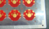
You can see the strip is cut right through the round fiducial like pads.
Doesn't make sense to have a V-groove on a single side of such a thin PCB though?
Zooming in on the lower right corner of the first picture, I think it says KS20151112S.
Could be 12 november 2015 or 11 december (depending on the format).
I
want to say it is, I really do ... but I can't accept that's a number '5'. The top left corner simply isn't square no matter how I squint my eyes.
/?action=dlattach;attach=215585;image)
(and the letter before it looks more like an 'I' than a '1' - "KS20IS", not "KS2015")
That are the EXIF data
So they are basically from Feb and March
For those interested here are the links to the higher res pictures:
These have full EXIF data, photos taken on the 3rd March.

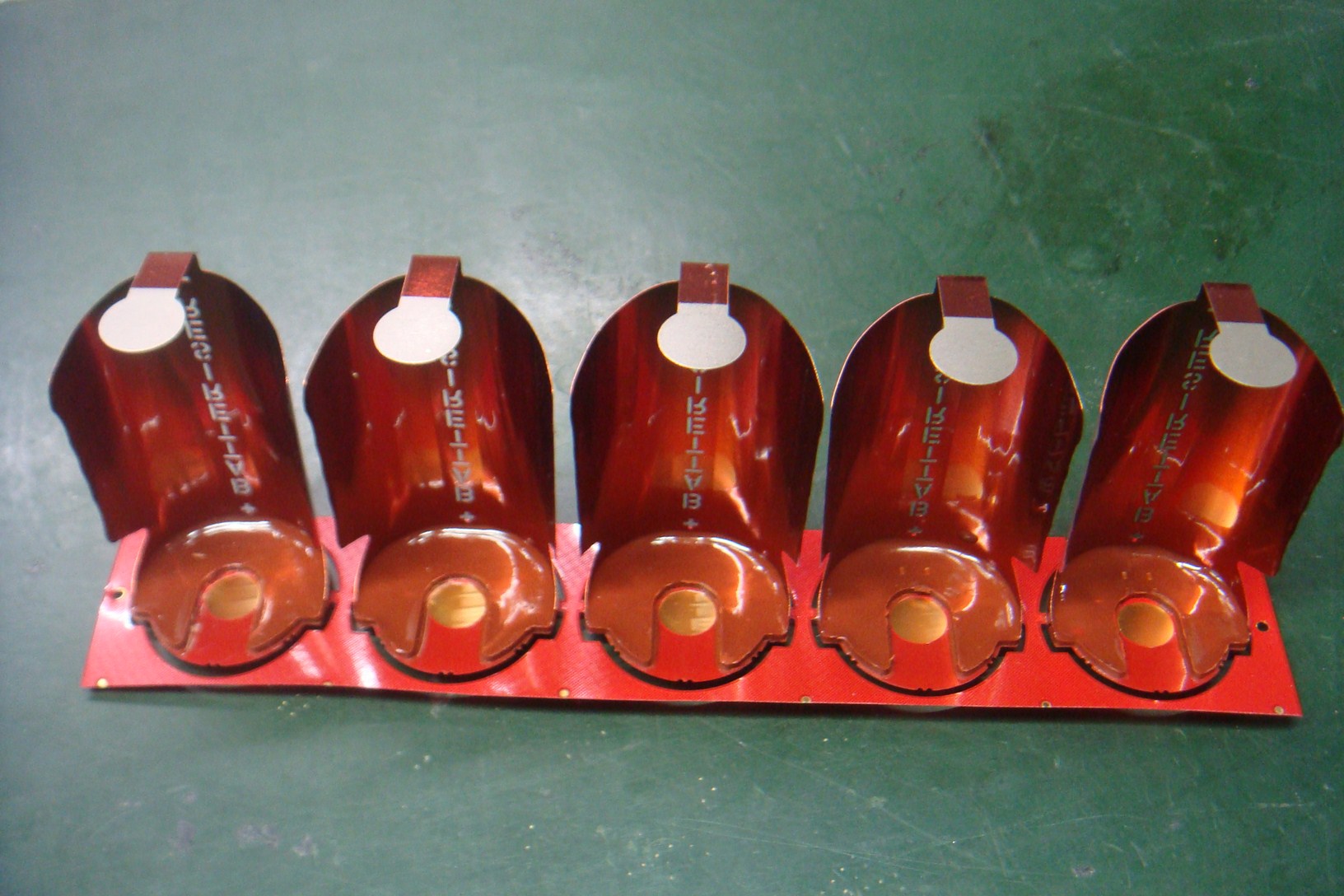
PCB seems very thin. Probably easy to break apart.
Looks like flex circuit to me.
PCB seems very thin. Probably easy to break apart.
Looks like flex circuit to me.
0.5mm and under PCB is very flexible.
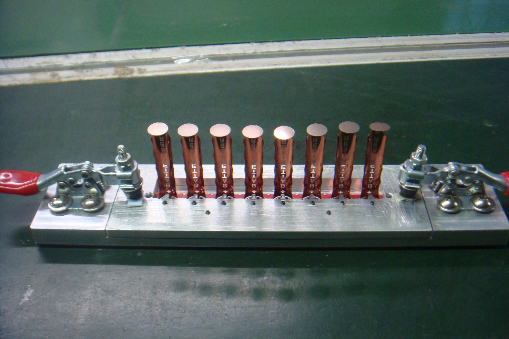
You can see warping on the D holder PCB panel:
How do the date 2016:03:03 06:21:41 correspond with WHEN Bob was leaving to China? Didn he say that they where going to China at a later time?
That was the 1st of April - everybody said "April Fools" when he announced it.
/?action=dlattach;attach=215596;image)
Bob doesn't claim to have taken the pictures himself, so...

There must be some components UNDER the PCB, since it floating a little over the table.
There has to be at least a 'battery button' under there or it won't be shaped like a battery.
For those interested here are the links to the higher res pictures:
These have full EXIF data, photos taken on the 3rd March.
...assuming they don't know about EXIF and hex editors.
Why that complicated?
You are able to change the Data to what ever you want in the Windows-Explorer.
Looks like flex circuit to me.
0.5mm and under PCB is very flexible.
Yeah but not THAT much, it's still fiberglass and you still need to hold some force to keep it warped. This one is anything but flat with no stress. Especially where it got "pinched" close to the little hole and kept its shape.
Why that complicated?
You are able to change the Data to what ever you want in the Windows-Explorer.
Oh, yes, so you can...

I tried it though and it mangles the EXIF info inside the file (moves things around). I can safely say that Windows Explorer wasn't used to change the dates.
I'd say the EXIF looks legit... woulld be too correct for what we can expect from them

I'd say the EXIF looks legit... woulld be too correct for what we can expect from them
I grudgingly agree.
A "positive" result doesn't prove anything either way though. They could be setting up for manufacturing, they could have pulled some old prototypes out of a closet and photographed them last month.
We need a "negative" result.
The camera used is slightly weird (most people these days would use a cellphone) but that doesn't prove anything.
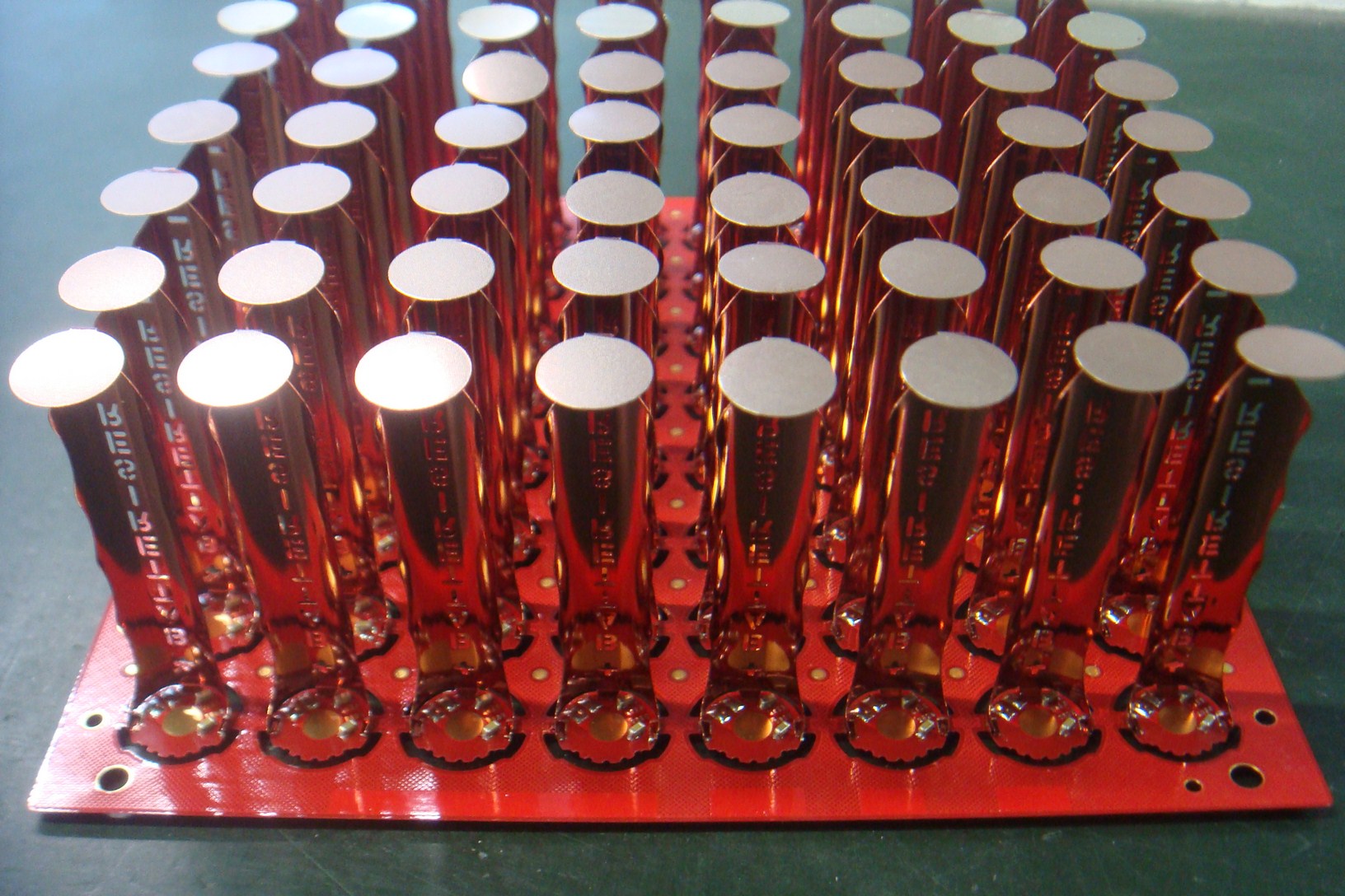
The only thing that really bothers me is the name "Batteriser" in those pics. They have the Energiser lawsuit hanging over them and a couple of months ago they changed the spelling on the prototypes they were showing (I can't find the pics of that, anybody remember where they are...?)
The only thing that really bothers me is the name "Batteriser" in those pics. They have the Energiser lawsuit hanging over them and a couple of months ago they changed the spelling on the prototypes they were showing (I can't find the pics of that, anybody remember where they are...?)
We kind of decided that they were from an earlier prototype:
/?action=dlattach;attach=193506;image)
Are there one sided v-scores? If so, board might be flipped, v-score on other side? Or maybe using a depanelizer?
I might have bad eyes..... wheres the converter?

If you look realy closely you can notice at least a "big" cap at the downright edge, just where the sleeve connects to the pcb, so I assume there is actually some circuitry on there. How well it works... we will see "soooooon" 
Curious because I thought the converter was the component needing redesign? I do think the park on the bottom right looks to be a passive. The pic is fairly low res unfortunately.
Guys... you're all missing something here...
Those PCBs are loaded with no IC... the pads are empty....