-
This reason is of course not trigger.
OK, a big part of that signal seems to be my horrible probing. I poked the bottom of the Arduino with the probe instead of clipping onto a the Dupont wire and it all got better.
Images have been removed to avoid wrong conclusions. If nobody steps up with a proper pulse generator+BNC then I might try again later with the little probe spring directly onto the AVR chip.
This "horrible" probing is not at all what I look. I can filter these kind of things out from thinking and look important things what I think are trigger jitter and alising and fact that of course it can not do ideal Sinc reconstruction what is not even suitable in practical oscilloscope because reconstruction need be fast and only over some true sampled points. And what I see there, there is signs of corners wobbling (one form of aliasing) and perhaps tiny part of Gibbs but then (not my thinking but you told) most parts of overshoot is in your signal.
These example images are old and not at all for compare. These are from "theory and practice lesson" where I try simply way demonstrate things not at all if scope is good or bad etc but common principles. (and not even perfectly if think scalability to more speed without also BW scaling accordingly).
Yes these are made using 1us sample period. No matter. It can scale.. Reason was just that I can very accurate control rise and fall times etc and range is well below BW so that sure enough harmonics are there and I know enough sure what ADC really see.
Important is. Risetime 3.5us fall time 1us. Sampling period 1us. Of course fall have strong alias but also there is 3.5 sample in rising edge and also there can see some corner wobble.
If rise and fall is 1.5 sample period corners wobble reduce lot of.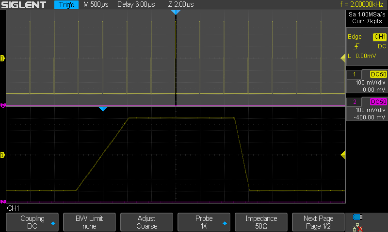
1 without any interpolation and acquisition slow so that just single acq samples are highlighted and previous acquistions are only stored by persistence (and every acquisition data points in random time shift interleaved because no sync with ADC clock so finally it produce continuous line). Rise 3.5 and fall 1 sample interval. (in fast mode of course it generate lot of more dots to every sequential TFT frame)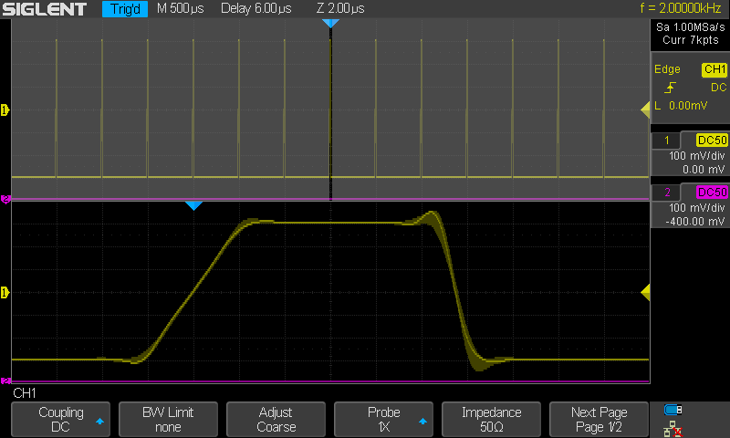
2 same with Sinc interpolation lines between dots on. Acq slow. (one acg per frame)
rise 3.5 and fall 1 sample interval (as can see result is... high amount sinc produced...)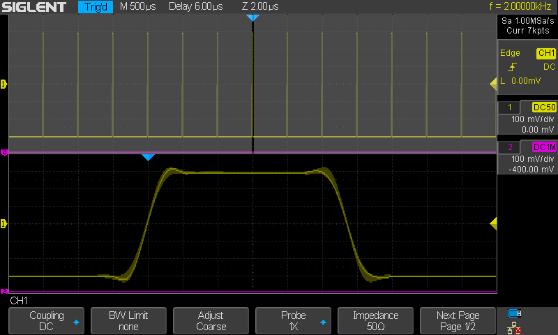
3. Sinc as image 2 and rise and fall 1.5 sample interval. Corners wobbling but lot of less than if rise or fall is 1 sample interval.
These effects can also detect in your images (quite sure) and they looks just normal. (sampling interval 4ns).
-
Well, I have not used those tools, but you're saying the result is the same? Data is shifted half a screen late and you missed half the pulse?
Yep.
-
Well, I have a vague recollection that Karel posted something about horizontal position being incorrect. Not sure if related to this issue. It can't be good. I can turn on my PG this evening, briefly. It's still connected too.
-
And what I see there, there is signs of corners wobbling (one form of aliasing) and perhaps tiny part of Gibbs
There's 130Mhz+ of signal going into something with Nyquist limit of 125Mhz. You can't expect perfection (or zero wobble!)
PS: What's going on at these corners?
-
This is turning into a "scopology" thread...
Time for me to unsubscribe from this thread,
and maybe time for some of you to take on an electronics project for a change?
-
and maybe time for some of you to take on an electronics project for a change?
You mean physically sniffing on Rigol's ADC ? Excellent idea, doubt that much more intel can be milked out from ack data
-
Previous raw data points (Dot mode) plus persistence.And what I see there, there is signs of corners wobbling (one form of aliasing) and perhaps tiny part of Gibbs
There's 130Mhz+ of signal going into something with Nyquist limit of 125Mhz. You can't expect perfection (or zero wobble!)
PS: What's going on at these corners?
Only can be done with a waveform source with low jitter and in true real dots mode. -
This is turning into a "scopology" thread...
Time for me to unsubscribe from this thread,
I think I'm done now.
I've learned a bit more about my DS1054Z.
(and I'm still perfectly happy with it!)
-
Previous raw data points (Dot mode) plus persistence.
Only can be done with a waveform source with low jitter and in true real dots mode.
OK, so a bit like this:
-
Yep, probing technique excused.Previous raw data points (Dot mode) plus persistence.
Only can be done with a waveform source with low jitter and in true real dots mode.
OK, so a bit like this:
......Pic.............
-
PS: What's going on at these corners?
I wasn't expecting such square corners. Is that what's expected? How close do we think these devices are representing the actual pulse waveform? Here is another sample.
-
I noticed my levels were way off. This is about the minimum level out of my old analog datapulse.
-
PS: What's going on at these corners?
I wasn't expecting such square corners. Is that what's expected? How close do we think these devices are representing the actual pulse waveform?
They are as in images show as exactly as can see in image. But, perhaps you forget read my original explanation about these example images. These are picked up from my "teaching" material where images can compare with each others (not for compare different equipment) for understand and see how things change related to sampling interval time and changes speed in signal. For this purpose I have made these using very low frequencies and then different interpolation and without and using different rise and fall times related to sampling interval time. With this method can go out from probing and analog front end and signal generator performance and look alone things what are handled in "lesson".
Why these images are here.
For show how corners wobbling is normal effect and exist also in Fungus image (what he have removed) and whjat are just normal due to his used sample interval, risetime and using Sinc interpolation. There eye can easy isolate these phenommenons and not mix these with trigger interpolation and acquisition fine adjust to right time position.
Previously:Quote from: FungusHere's the same thing with sin(x)/x off. Triggering is much tighter:
I'm not sure what conclusions can be drawn with my really crappy probing though.Quote from: rf-loopThis reason is of course not trigger.
OK, a big part of that signal seems to be my horrible probing. I poked the bottom of the Arduino with the probe instead of clipping onto a the Dupont wire and it all got better.
Images have been removed to avoid wrong conclusions. If nobody steps up with a proper pulse generator+BNC then I might try again later with the little probe spring directly onto the AVR chip.
This "horrible" probing is not at all what I look. I can filter these kind of things out from thinking and look important things what I think are trigger jitter and alising and fact that of course it can not do ideal Sinc reconstruction what is not even suitable in practical oscilloscope because reconstruction need be fast and only over some true sampled points. And what I see there, there is signs of corners wobbling (one form of aliasing) and perhaps tiny part of Gibbs but then (not my thinking but you told) most parts of overshoot is in your signal.
These example images are old and not at all for compare. These are from "theory and practice lesson" where I try simply way demonstrate things not at all if scope is good or bad etc but common principles. (and not even perfectly if think scalability to more speed without also BW scaling accordingly).
Yes these are made using 1us sample period. No matter. It can scale.. Reason was just that I can very accurate control rise and fall times etc and range is well below BW so that sure enough harmonics are there and I know enough sure what ADC really see.
Important is. Risetime 3.5us fall time 1us. Sampling period 1us. Of course fall have strong alias but also there is 3.5 sample in rising edge and also there can see some corner wobble.
If rise and fall is 1.5 sample period corners wobble reduce lot of.
-
I wasn't expecting such square corners. Is that what's expected? How close do we think these devices are representing the actual pulse waveform? Here is another sample.
Note that the sample rate in that image is only 1Msa/s and it's not a pulse (it's a slope). The reason the corners are so square is because of the huge bandwidth discrepancy between the analog bandwidth of that oscilloscope and the sampling rate being used (1000:1 ratio). This gives it the equivalent of a brickwall filter on the input.
ie. It's a sales demo, deliberately staged to fool people (and to be difficult to reproduce at home).
In this image the input is a much faster pulse and sample rate is 250Msa/s, you have input frequences well above the analog bandwidth of the front end, etc. That's why it isn't square.
-
As promised I re-did those images using the spring clip directly onto the pins of the AVR chip (Arduino Uno, DIP-28 package). Ringing is much reduced(!)
Here's sin(x)/x on/off in dots mode. Four channels enabled, 250MSa/s:
With better probing, sin(x)/s ON seems to show less Gibbs than OFF. With bad probing it was the other way around. Go figure.
For reference, this is how much ringing there was with breadboard wires poked into the edge connector:
-
Note that the sample rate in that image is only 1Msa/s and it's not a pulse (it's a slope). The reason the corners are so square is because of the huge bandwidth discrepancy between the analog bandwidth of that oscilloscope and the sampling rate being used (1000:1 ratio). This gives it the equivalent of a brickwall filter on the input.
ie. It's a sales demo, deliberately staged to fool people (and to be difficult to reproduce at home).
No. It is NOT sales demo at all. What you win with this kind of bullshit. Perhaps I know better whjat I have done than you. So please do not explain some your own story about what I have done and why.
You can not read what I previously told about these images nature and what for these images are.
If you want see original material where from they are you perhaps understand better they are not at all sales demo purpose.
But this material where from images are is finnish language so you can not understand it due to fact that finnish language is like "enigma" for example google translator. And I have also explained previously why I pick up these images here. If you really do not understand then tell it directly that you did not understand instead if this indirect way tell same.
This (one part) of "teaching" material for peoples who do not have so much knowledge about digital oscilloscopes. Some kind of common bottom entry level information. Examples are made using Siglent but all these can do using nearly what ever this era entry level digital oscilloscope.
Send me this your Rigol I do same with it and then change these images if you are then more happy.
"This gives it the equivalent of a brickwall filter on the input."
Then this is total bullshit. It tell that you really do not understand. This acts just opposite. Related to sampling speed now analog BW before ADC is nearly like super wide so that ADC can see (and there is used it) up to very high over Nyquist. (also I have explained why I want ADC can see lot of over Nyquist...
We need know things but more important is also understand things. Thinking is still not old-fashioned though we have youtube and internet and are able to see a lot of things without thinking about anything.
-
I didn't mean "sales demo" in the literal sense. I meant "deliberately chosen parameters" to show the best possible result.
Maybe I was too subtle. I apologize.Related to sampling speed now analog BW before ADC is nearly like super wide so that ADC can see (and there is used it) up to very high over Nyquist. (also I have explained why I want ADC can see lot of over Nyquist...
Maybe it's a language thing, this is what I meant. This is the reason the corners are nice and square compared to the other image that was posted.
-
For completeness, here is the same probing with less channels enabled.
One channel:
Two channels:
-
Could what Fungus is doing considered as oversampling? Otherwise it is quite weird that rise time stays ~const (on all Sinc=ON examples).
If Photoshop a little rf-loop example it can be seen that averaged low-samplerate ack could not ever match true risetime:
Same seen here. Top one is heavy oversampling, bottom is persistence on non-oversampled. Averaging bottom one would not result in top one.
-
Could what Fungus is doing considered as oversampling?
Me? I'm not doing anything.Otherwise it is quite weird that rise time stays ~const (on all Sinc=ON examples).
Isn't that what sinc filter is for?
Edit: Maybe that's the true rise time of a pin on an Arduino Uno after all the capacitances, etc. have been taken into account. We need somebody with a better oscilloscope to measure one.
-
Isn't that what sinc filter is for?
If you look then in rf-loop example Sinc is ON yet averaging it could not result in true trace. Same seen on ETS+RTS scopes: ETS with ludicrous sample rate gives some margin over no-matter-how-good-sinced RTS. I'm sure there must be some theoretical explanation behind this...
-
If you look then in rf-loop example Sinc is ON yet averaging it could not result in true trace.
Of course not. The signal isn't bandwidth limited to the Nyquist cutoff at that sample rate.
The error in the reconstructed signal (due to aliasing/Gibbs) will be slightly different for each horizontal sample position, yes?
So... you get this if you reconstruct the signal at every horizontal sample position then overlay all the images:
-
This is the reason the corners are nice and square compared to the other image that was posted.
And in my first message with these images I emphasised that they are not for compare...
Only what can compare are my two images with each others and note how things change when samplinc period time/risetime ratio change.
Also you toldQuote from: Fungus(and to be difficult to reproduce at home)
How this can be difficult. There is nothing difficult at all. If this is difficult then...<advance censored>.
Just simple basic simple generator and basic simple scope, one cable and turn knobs.
Btw, trigger jitter (when signal violate Nyquist rules etc) is other question but is was not shown with these two images. It start seriously rise when signal risetime what ADC can see is around equal or more if clearly less than sample period. Also this is natural (and makes full digital side trigger engine different if compare good analog side pathway trigger system in DSO/DPO it can nearly say (least if we talk today entry and middle level realtime digital scopes)
This can say is nearly like some kind of "achilles heel" of this kind digital side trigger system, not problem if user understand and can avoid this kind of situations in use or least that he recognize this situation)
In some special cases true dots mode can help, depending how its is implemented in system. But these are perhaps somehow explained in future in "lesson 2" if nothing more important is in "to do" list.
I want oscilloscope where is "brick wall style" filter in analog side (what is only place for it. It can not be in digital side) so that corner frequency is automatically (or manually selectable) adjusted with current sample rate and what user can switch on or off and stay with common "gaussian type" BW.
example about undersampling and Sinc horizontal time jitter (one kind of trigger jitter)
and other image same signal same trig but dots (randomly interleaving acquisitions, not ETS) and waveform shape and positioning without huge jitter)
This is why it is good to have opportunity to always turn all interpolations off (exept trigger engine internal "what ever"...). Just because only real data what we have are true sample points level and time and nothing else. Independent of what Keysight or who ever talks. There money talks.
In images of course they are still images so they do not looks same (specially dots mode) as it looks when human brain+eye handle sequential TFT frames. (also intensity gradation process have less position collisions in dots mode so it can not produce same as Sinc or Linear. But scope is tool, not for beautiful images generator.)
-
How this can be difficult. There is nothing difficult at all. If this is difficult then...<advance censored>.
Just simple basic simple generator and basic simple scope, one cable and turn knobs.
I don't have such a generator, most hobbyists don't.
-
This is why it is good to have opportunity to always turn all interpolations off (exept trigger engine internal "what ever"...). Just because only real data what we have are true sample points level and time and nothing else. Independent of what Keysight or who ever talks. There money talks.
Even a sinc function will show square corners on a slow signal like that if you use the full 1GSa/sec.
Even at 100MSa/s there will be 99 more samples between each dot in the image, sinc will be fine with that.