-
Could the the noise you see on Ch1 be related to the MCU clock ?

The last screenshot (channel 1) is taken at 1V/div - looks good, the second screenshot - the channel 1, taken at 5V/div => ver. sensitivity has been changed to 1V/div - it looks strange => it must be the same as the last screenshot, period. MCU has nothing to do with it, I used the signal generator with the same result.I know there are occasions when a STOP, Single or screenshot displays things that take some understanding
Agree, and knowing that this is why I spent some time on Sunday evening to make it easy to understand and what is more easy to reproduce.
-
Hi,
I wonder what I am observing here - a bug in the latest stock firmware (7.0.6.1 25R2) or something else. I noticed that every time when I zoom in (change vertical sensitivity) on the recorded signal it looks quite noisy. Eventually I simplified the test to avoid any ambiguity and this is the result:
a) the signal source (MCU) with stable power supply generates 50 pulses. The channel 4 monitors power line. The SDS1204X-E is single trigger mode, 5V/div, the signal is applied to channel 1
b)now lets change the scale to 1V/div - the signal looks quite noisy and I know that this is not true.
c) another recording of the same signal, SDS1204X-E is in single trigger mode, 1V/div, the signal looks as it should be. The only difference a c is the vertical sensitivity.
My question is - what is this wrong with displaying the previously recorded signal when the vertical sensitivity has been changed ?
Thanks!
Before I start tell basic fundamentals how digital oscilloscope works (and what you have meet here) I want you tell me why your first image display 20MSa/s because if you did as you tell, this 20MSa/s with 14Mpts is not possible at all when t/div is 100us/s. Is it possible you have captured it using 50ms/div and after then zoomed in? What other things, if any, you coincidentally forget to tell?
Is it so that everything user do not understand is the manufacturer's fault?
I can give one tip first. ADC is 8bit.
In the main, this is a problem in education, not in the oscilloscope.
Here we can work together to study, shorter and longer courses about basic fundamentals of oscilloscopes.
-
Before I start tell basic fundamentals how digital oscilloscope works (and what you have meet here) I want you tell me why your first image display 20MSa/s because if you did as you tell, this 20MSa/s with 14Mpts is not possible at all when t/div is 100us/s. Is it possible you have captured it using 50ms/div and after then zoomed in? What other things, if any, you coincidentally forget to tell?
Honestly, I have no clue what you are asking for. What else do you want to hear?
Is it possible that I captured the signal using XX ms/div and after that changed the horizontal scale to YY us/div? Yesterday I took about 30 different screenshots while was trying to understand what I was looking at and I was changing the H and V scales whenever I needed. But I don't think that it has a big relevance in _this (please note the underscore sign, which is supposed to have some meaning in this context) particular case because anyway we had high enough sampling rate and we are mostly interested in vertical resolution and all contributing factors (XX bit ADC, the dynamic range of the amplifier (if there is any) + ADC resolution, the type of the used amplifier - it can be a fixed gain or variable gain amз etc - all that would affect the final/full dynamic range of the system - I don't have any knowledge about SDS 1204 internal implementation -> that is why I asked this question on the forum in the first place) leading to the observed effect.Is it so that everything user do not understand is the manufacturer's fault?
If I could suggest then I would suggest that you reread my original post which started from the sentence "I wonder what I am observing here - a bug in the latest stock firmware (7.0.6.1 25R2) or something else." Where have I said about "manufacturer's fault? in assertive mannerI can give one tip first. ADC is 8bit.
In the main, this is a problem in education, not in the oscilloscope.
Here we can work together to study, shorter and longer courses about basic fundamentals of oscilloscopes.
You have edited your message 2 times after posting it by adding 3 last lines filled with valuable info.Before I start tell basic fundamentals how digital oscilloscope works
No need, thanks. Now I know that the used ADC is 8 bit and this is probably the culprit. Why probably? Because like I already mentioned I think the ADC resolution is not the only factor that matters in this case.
The most important conclusion (for me) is that if I run all 4 channels (i.e. 2 ver. div for a channel) at once and observing TTL level signals (i.e. I use 5V/ div) then after I captured the event I am interested in and try to zoom in by changing vertical scale I am going to see some of non-existing noise which is just the result low overall resolution of used ADC and other contributing factors. I wonder how much difference I would see in a similar situation (the screen is 8 ver. div, 4 channels are running, the ver. sensitivity is 5V/div, the captured signal is examined at 1V/div) with a o-scope using 12bit ADC. I actually have a 16 bit o-scope, sitting nearby so I may try it for comparison purposes.
-
So I must say that I am very impressed with this scope, especially with the extended bandwidth. Definitely an amazing value for the price.
While that's not a bad idea, lighting in a workplace present or not could effect the usability of dual illumination of buttons. I suspect it couldn't be done with SW but we'd have to check the front panel HW to know for sure.
One thing that I have noticed is that when I am using multiple channels, I would really like to have the channel buttons for each channel being displayed to be lit up, e.g. if I am measuring waveforms with channels 2 and 3, I would like the physical buttons to be lit up for channels 2 and 3. I realize that this might conflict with fact that the active channel is lit up, but perhaps the active channel button could cycle between a bright and dim state to accommodate that feature.
Personally I would be against of such modification, I really like the way the channel button's logic works right now. What would the proposed change give? To indicate what channels are activate? But there are channel indicators on the screen, plus in some situations (depends on the used trigger mode) the visible signals (in different color) immediately give you the idea what channels are enabled. The situation would be different if they have not used multiplexed vertical controls but we have what we have.
I am definitely not proposing any changes to the UI displayed on the screen, which in my estimation functions rather well. The purpose of the proposed change would provide exactly what you just described: an additional indicator of what channels are active. I acknowledge that there are some indications on the screen about what channels are active, but there are situations when it is not as obvious.
One of those situations occurs when a non-active channel is turned on but possesses an amplitude offset that takes it off screen. If the trigger is set to a channel that does not correspond to the off-screen signal, the only two indicators that the channel is indeed on are the channel box on the right hand side of the screen, and a small colored arrow indicating that it is off-screen. It is my opinion that it can be easily missed that the channel has been turned on. I have attached a copy of an image demonstrating this scenario in this message.
I realize that after a large number of hours working with this device that this issue may be mitigated by experience, but it seems to me that having each channel that is currently in use to have its associated push button lighted is a reasonable way to make it totally clear which channels are turned on and which ones arent. For the active channel, I acknowledge that cycling between a bright and dim state for the push button may not be possible or easily overlooked, so perhaps cycling between on and off states would be a fair compromise.
This capability is actually already present in Rigol, Rohde & Schwarz, and Keysight oscilloscopes, and is really quite nice:

-
[ It is my opinion that it can be easily missed that the channel has been turned on. I have attached a copy of an image demonstrating this scenario in this message.
Hi SMB784,
could you please double check if you forgot to attach the aforementioned image?
Thanks! -
[ It is my opinion that it can be easily missed that the channel has been turned on. I have attached a copy of an image demonstrating this scenario in this message.
Hi SMB784,
could you please double check if you forgot to attach the aforementioned image?
Thanks!
Yep sorry just attached it! -
As you wrote earlier:[ It is my opinion that it can be easily missed that the channel has been turned on. I have attached a copy of an image demonstrating this scenario in this message.
Hi SMB784,
could you please double check if you forgot to attach the aforementioned image?
Thanks!
Yep sorry just attached it!QuoteI realize that after a large number of hours working with this device that this issue may be mitigated by experience
This is the key here, but not a 'large number of hours', only a little time to look at the display with a little more analytical mind.
Other than the 2 indicators you've mentioned (zero level marker and channel ON box) there's also the zero level indicator in the channel box that when compared with the V/div setting indicates the waveform will obviously be off the display. When you find yourself in this situation a press of the Position control returns the active channel to the 0V position to where you can place it where it suits best.
Much of this is just familiarity with the UI, is it right or wrong or just another way to do the same operations as any other DSO ? They are all different in some way or another.
Compared to the other scope images you've posted I ask which has the most prominent active channel box on the display ? -
As you wrote earlier:
QuoteI realize that after a large number of hours working with this device that this issue may be mitigated by experience
This is the key here, but not a 'large number of hours', only a little time to look at the display with a little more analytical mind.
Other than the 2 indicators you've mentioned (zero level marker and channel ON box) there's also the zero level indicator in the channel box that when compared with the V/div setting indicates the waveform will obviously be off the display. When you find yourself in this situation a press of the Position control returns the active channel to the 0V position to where you can place it where it suits best.
Much of this is just familiarity with the UI, is it right or wrong or just another way to do the same operations as any other DSO ? They are all different in some way or another.
Compared to the other scope images you've posted I ask which has the most prominent active channel box on the display ?
I definitely concur that after a few days/weeks of familiarity that one becomes used to looking for active channels in the channel box, however there are a few things that I will point out.
The first and foremost of these is the fact that in a display a little redundancy goes a long way when it comes to ease of use. In this situation, nothing is sacrificed and in order to further emphasize the channels being used in an obvious and unambiguous way.
Secondly, there is the visibility aspect. It is difficult to see the on screen channel indicators from a distance beyond a couple feet. This is especially problematic when you have less than four but more than one channel activated, as it is possible to see that two/three channels are on from the channel box but it's difficult to tell which ones specifically are active. A lighted button for each active channel would make this completely unambiguous at any distance or viewing angle.
Finally, there is the mainstream appeal factor. You sacrifice nothing in opting for this feature and it makes your scope more familiar to those who are used to other competing scopes, which may improve your appeal.
Regardless it's not a huge deal, and I do love the scope, but the OCD in me made me bring it up, especially given that it is a feature that I know and love after having used scopes from just about every manufacturer there is -
As you wrote earlier:
QuoteI realize that after a large number of hours working with this device that this issue may be mitigated by experience
This is the key here, but not a 'large number of hours', only a little time to look at the display with a little more analytical mind.
Other than the 2 indicators you've mentioned (zero level marker and channel ON box) there's also the zero level indicator in the channel box that when compared with the V/div setting indicates the waveform will obviously be off the display. When you find yourself in this situation a press of the Position control returns the active channel to the 0V position to where you can place it where it suits best.
Much of this is just familiarity with the UI, is it right or wrong or just another way to do the same operations as any other DSO ? They are all different in some way or another.
Compared to the other scope images you've posted I ask which has the most prominent active channel box on the display ?
I definitely concur that after a few days/weeks of familiarity that one becomes used to looking for active channels in the channel box, however there are a few things that I will point out.
The first and foremost of these is the fact that in a display a little redundancy goes a long way when it comes to ease of use. In this situation, nothing is sacrificed and in order to further emphasize the channels being used in an obvious and unambiguous way.
Secondly, there is the visibility aspect. It is difficult to see the on screen channel indicators from a distance beyond a couple feet. This is especially problematic when you have less than four but more than one channel activated, as it is possible to see that two/three channels are on from the channel box but it's difficult to tell which ones specifically are active. A lighted button for each active channel would make this completely unambiguous at any distance or viewing angle.
Finally, there is the mainstream appeal factor. You sacrifice nothing in opting for this feature and it makes your scope more familiar to those who are used to other competing scopes, which may improve your appeal.
Regardless it's not a huge deal, and I do love the scope, but the OCD in me made me bring it up, especially given that it is a feature that I know and love after having used scopes from just about every manufacturer there is
It's nice to have a discussion where we can explore POV's and I fully get what you're asking here but I'd ask that if all active channels ON/OFF buttons were lit, how could the user know which one was active for the vertical controls ?
Would you have to press one again to set it to the vertical controls ?
This is what 17_29bis was meaning when he said he thought the existing channel management/indication logic was good.
Others ? -
It's nice to have a discussion where we can explore POV's and I fully get what you're asking here but I'd ask that if all active channels ON/OFF buttons were lit, how could the user know which one was active for the vertical controls ?
Would you have to press one again to set it to the vertical controls ?
This is what 17_29bis was meaning when he said he thought the existing channel management/indication logic was good.
Others ?
My suggestion to solve the problem of which channel is active was to have the lighted button for the active channel cycle between a dark (or dim) state and a bright state, perhaps at a 1-2 Hz rate. -
My Rigol DS1102CD also lights the buttons of all active channels, and you have to search for the active channel indication on the screen to see which one is selected. Uncertainty about the selected channel happens to me infrequently enough that I don't automatically look at the right place, yet sufficiently often that I remember it as a bit of a nuisance. Not sure if having only the selected channel lit would work better for me, but it does seem to be a more logical choice. I'm also not sure if I'd really want to have it blink. Of course, Siglent could just implement all three options, all active, only selected, both with blinking.
I'm a bit confused about the proposed use case: measure a non-active channel that is also off-screen ? Is there a "non" too many ?
Regarding measuring off-screen waveforms, how well does that actually work ? I would expect the scope to set the ADC range to cover mainly the screen, so the measured signal may be clipped or suffer other distortions ? Or does the Siglent let you choose screen position and DC offset independently ? -
I'm a bit confused about the proposed use case: measure a non-active channel that is also off-screen ? Is there a "non" too many ?
Regarding measuring off-screen waveforms, how well does that actually work ? I would expect the scope to set the ADC range to cover mainly the screen, so the measured signal may be clipped or suffer other distortions ? Or does the Siglent let you choose screen position and DC offset independently ?
The image I posted wasn't related to actually using an off screen waveform, rather it was posted to highlight the fact that there can be situations where I forget what channels are actually turned on, and one of those situations is when the channel is turned on corresponding to a waveform that is off screen. In that situation I am left wondering whether or not I have actually turned on the channel. Of course this can be remedied by looking at the channel box on the right, which I will have to train myself to do. -
I'm a bit confused about the proposed use case: measure a non-active channel that is also off-screen ? Is there a "non" too many ?
Regarding measuring off-screen waveforms, how well does that actually work ? I would expect the scope to set the ADC range to cover mainly the screen, so the measured signal may be clipped or suffer other distortions ? Or does the Siglent let you choose screen position and DC offset independently ?
Exactly my thought. If my memory serves me well someone (the one who knows the ropes) on this forum already said that if the oscillogram/waveform does not fit the screen then it's most likely / almost guarantied that the measurements on this channel will be incorrect i.e. it has no practical use. -
I'm a bit confused about the proposed use case: measure a non-active channel that is also off-screen ? Is there a "non" too many ?
Regarding measuring off-screen waveforms, how well does that actually work ? I would expect the scope to set the ADC range to cover mainly the screen, so the measured signal may be clipped or suffer other distortions ? Or does the Siglent let you choose screen position and DC offset independently ?
Exactly my thought. If my memory serves me well someone (the one who knows the ropes) on this forum already said that if the oscillogram/waveform does not fit the screen then it's most likely / almost guarantied that the measurements on this channel will be incorrect i.e. it has no practical use.
ADC full range is ~10div display vertical height is 8div.
Out of display there is around 1 div area for signal out of top and bottom of display. This area is not linear at all, as can see in next images. It can say that around 7div have good linearity and 6div have "perfect" linearity. Here two images what may tell some things.
Of course some can say linearity is nice if it is better. Yes also I can say it but then... if one ask that is it nice if there is very hard sharp clip due to ADC. Then I answer immediately that no. It need also rmember that we have here front end amplifier what need be cheap and what need do 500µV - 10V/div and from DC to least 200MHz with quite low noise and enough linear vs freq.
It can just say, without going details and reasons and reasons behind reasons and so on... it can say simply. This is compromise between many things and with it need live - if can not then some other. All like ideal but when we go more and more close to ideal it also means that price rise exponentially.
Also later (after I have more free time to this hobby playing) some things when some signal is captured to memory and then stopped and zoomed vertically in and horizontally in including also dots and vectors with Sinc on and off
Here these ramp images.
178 original acquisition with 50mV/div and then stopped
179 after stopped then vertically zoomed out to 100mV/div Now one vertical div is just 2 vertical div in original. (red ramp is imagined, not captured, how original signal looks like if scope is ideal machine)
-
Here these ramp images.
Thanks a lot ! These images show very clearly what I suspected would go wrong when pushing these limits. SMB784's use case may still work, but would require prior characterization of scope performance for the exact set of settings to be used.
By the way, I find it interesting that one can already see a hint of non-linearity in the top and bottom parts of image 178. That shows how narrow the margins really are.
Fun ideas for when someone gets around to writing alternative firmware for a scope:
- add optional warnings when waveforms get clipped, especially if measurements are active that would be directly affected,
- if moving parts of a waveform with high distortion onto the screen, visually indicate that these parts can't be trusted,
- add (optional) auto-ranging of front end configuration to capture entire amplitude,
- allow manual control of ADC of front end configuration, including separate control for DC offset and screen position,
- per-channel intensity control so that one can just hide active channels one doesn't want to look at (i.e., the real issue SMB784 is trying to solve).
Especially the first two could help less experienced users in situations where the scope is doing something that's very different from what they think it should be doing. -
Here these ramp images.
Thanks a lot ! These images show very clearly what I suspected would go wrong when pushing these limits. SMB784's use case may still work, but would require prior characterization of scope performance for the exact set of settings to be used.
By the way, I find it interesting that one can already see a hint of non-linearity in the top and bottom parts of image 178. That shows how narrow the margins really are.
Fun ideas for when someone gets around to writing alternative firmware for a scope:
- add optional warnings when waveforms get clipped, especially if measurements are active that would be directly affected,
- if moving parts of a waveform with high distortion onto the screen, visually indicate that these parts can't be trusted,
- add (optional) auto-ranging of front end configuration to capture entire amplitude,
- allow manual control of ADC of front end configuration, including separate control for DC offset and screen position,
- per-channel intensity control so that one can just hide active channels one doesn't want to look at (i.e., the real issue SMB784 is trying to solve).
Especially the first two could help less experienced users in situations where the scope is doing something that's very different from what they think it should be doing.
Guys you are mischaracterizing what I said. I never said that I intended to take measurements from a trace off screen, and I certainly do not want to solve any issue about HIDING active channels. What I said was that sometimes when you switch to a different channel after turning on a channel whose trace happens to be off screen (maybe even by accident), it can be difficult to determine at a quick glance whether or not you have actually turned on the channel without a lighted button for that channel.
My statement was an argument for a lighted button for each channel that has been turned on, as opposed to the current configuration that only has a lighted button for the currently active channel. Nothing more than that. -
rf-loop:
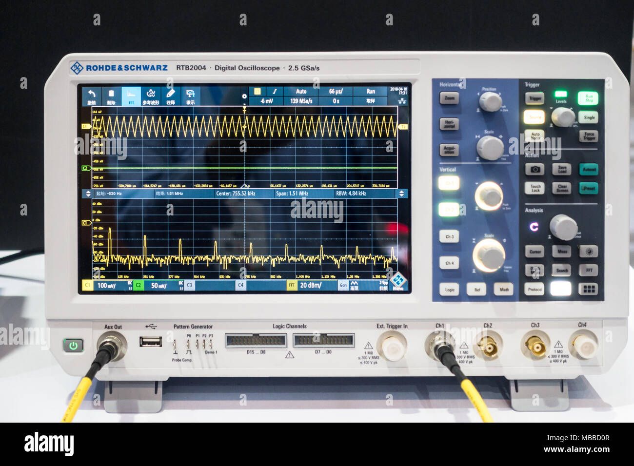
R&S RTB2k (and I assume their higher end siblings) do the first three of these ideas. You get little red arrows on the channel info bar when clipping (pointing up, down or both depending on clipping direction), a hard cut-off edge to the waveform in orange when moving it up/down the screen after capture and measurements will show "clipping+" or "clipping-" when used on a clipped waveform.
Definitely agree about being able to decouple ADC range from 1:1 mapping to screen display range - some scopes allow for the ADC range to cover a smaller portion of the screen so that you can "stack" waveforms for better visibility without reducing the captured resolution, but these scopes seem to be few and far between (I think the new Tek scopes do this, but others have in the past too despite the Tek marketing droids claiming it as revolutionary).
SMB784:
Again comparing to the RTB2k (and also the new Tek scopes) - this does what you want (enabled channels have lit LEDs behind their respective panel buttons), but this scope also has the ability to light up the knobs with the currently selected channel's colour (via RGB LEDs behind the panel). This means that you can tell BOTH which channels are on and which channel is currently selected for adjustment - unfortunately hard to do without the multicoloured LED thing or referring to the screen. Without this it's always going to be a compromise as to how the use the channel button LEDs - it's never going to be right for everyone. Both of my examples are well above the Siglent price point though (and have their own quirks) so I think it's hard to criticise a few compromises and limitations like this! -
rf-loop:
R&S RTB2k (and I assume their higher end siblings) do the first three of these ideas. You get little red arrows on the channel info bar when clipping (pointing up, down or both depending on clipping direction), a hard cut-off edge to the waveform in orange when moving it up/down the screen after capture and measurements will show "clipping+" or "clipping-" when used on a clipped waveform.
Definitely agree about being able to decouple ADC range from 1:1 mapping to screen display range - some scopes allow for the ADC range to cover a smaller portion of the screen so that you can "stack" waveforms for better visibility without reducing the captured resolution, but these scopes seem to be few and far between (I think the new Tek scopes do this, but others have in the past too despite the Tek marketing droids claiming it as revolutionary).
I hope some day we can see Siglent add also this warning about clipping or possible clipping warning (and add bit more wide analog front end linear range before ADC and then accept more sharp clipping (what produce lot of harmonics and for avoid this, there need be warning about clipping - of course also now this warning is good to have (example so that there is bottom and top some band and ADC data show signal there --> warning.)
Of course it is nice to wish and more nice to see many things... like free lounges..SMB784:
Again comparing to the RTB2k (and also the new Tek scopes) - this does what you want (enabled channels have lit LEDs behind their respective panel buttons), but this scope also has the ability to light up the knobs with the currently selected channel's colour (via RGB LEDs behind the panel). This means that you can tell BOTH which channels are on and which channel is currently selected for adjustment - unfortunately hard to do without the multicoloured LED thing or referring to the screen. Without this it's always going to be a compromise as to how the use the channel button LEDs - it's never going to be right for everyone. Both of my examples are well above the Siglent price point though (and have their own quirks) so I think it's hard to criticise a few compromises and limitations like this!
Channels what are active is always displayed with information box right side of display and also marked with channel color. There is channel number what can not see far away but there is also channel color, what I can see least many meters distance even when my eyes are bad and quite old. Even if I turn all active traces out from display I can see what are active channels turned on, and of course also what channel is selected for adjustments. These 4 buttons have channel colored leds.
(but still I think display is better if do not turn off this information box in display. Only make it bit more dark gray (and no colors) and keep these text visible so I know even without turning channel on what are this channel current settings (some times it is possible nice to know) but more I think that it is more ergonomy if these information boxes vertical positions do not change depending what are selected on or off.
How ever I think and investigate this question with scope and different environments I still can not imagine how there can be any - even small - difficult to immediately know what channels are active on and what channel is selected for adjustments. No need even read anything, even the peripheral part of the field of vision is sufficient for observation.
Except in one also important situation: And this is: if user have some mode of some kind of color detection problems in eyes (also this is solved if off channels info box still stay in place but without colors and some amount dimmed.) Or some other rare specific perception problem but then need question, how far we need go to some very extremely rare specialities in usability.
Perhaps also in some special lightning situations but they are not very common in normal lab environment. -
I've been running some tests, both to familiarize myself with the operation of the scope and to measure a few things which are cumbersome to do with a less capable piece of test gear. And while I'm glad to have so much functionality in the scope, sometimes things which are very different in operation from an old analog unit cause me some confusion.
Here's a test of a Class D audio amp. You can't measure the output directly with a common-ground scope because the outputs float. So the easy workaround is to use two channels (3-4) and Math mode to difference them. That seems to work fine. But I've seen a couple of puzzling things and I'm sure it's just my inexperience with a DSO which is hampering me.
1) The manual says "if the analog channel or the math function is cut off (waveforms do not display on the screen completely), the resulting math will also be cut off." Fair enough - though I wish the Math function was implemented earlier in the processing chain. But in order to get good resolution on the Math calculation, I need to have the sensitivity set high enough on the two amp output channels so that I don't get bit truncation on the math (I tried it with lower sensitivity on CH3-4 and the Math waveform was really ugly). This causes the CH3-4 waveforms to go off the screen, and as you can see in the screenshot, the Math waveform is already starting to show the effects of this.
2) So I can't move the waveforms offscreen and if they're onscreen the display gets really cluttered. For some types of analysis, I really don't want to see CH3-4 on the screen - it prevents me from getting a good look at the output; however, I can't find anything about an option to turn off display of an active channel. What am I overlooking?
-
Greg, are you using the webrowser to control the scope or just to grab the screenshot ?
To reduce the display clutter can you use a lower sensitivity setting (V/div) on all channels, Maths included. ? -
I'm just using it for a screenshot because I can go to my upstairs computer and capture without fussing around with a USB drive; all my operations were done from the front panel.
The problem with reducing sensitivity is that when I turned down sensitivity on CH3-4 for this test, the Math waveform degraded substantially. IMHO it's using the lower values (post-attenuation) to calculate the waveform and if the amplitude of the source channels displayed is too low, the Math waveform suffers badly from bit truncation. I can post an example of this if it's not clear what I'm describing.
Meanwhile, I found that turning the trace brightness down affects everything except the Math waveform, so that is a workable alternative - again, unless I am overlooking an option. -
I'm just using it for a screenshot because I can go to my upstairs computer and capture without fussing around with a USB drive; all my operations were done from the front panel.
Hmmm
The problem with reducing sensitivity is that when I turned down sensitivity on CH3-4 for this test, the Math waveform degraded substantially. IMHO it's using the lower values (post-attenuation) to calculate the waveform and if the amplitude of the source channels displayed is too low, the Math waveform suffers badly from bit truncation. I can post an example of this if it's not clear what I'm describing.
Meanwhile, I found that turning the trace brightness down affects everything except the Math waveform, so that is a workable alternative - again, unless I am overlooking an option.
Memory depth might be your issue here and it's related to timebase settings.....can you still work with a slower timebase setting ? -
No, I've tried setting the timebase to extreme values and it doesn't change at all. It really does look like the Math function is working with too little vertical resolution on the source waveforms. At the sensitivity I'm using here they look pretty pixilated as well, though the input signal is fine.
-
No, I've tried setting the timebase to extreme values and it doesn't change at all. It really does look like the Math function is working with too little vertical resolution on the source waveforms. At the sensitivity I'm using here they look pretty pixilated as well, though the input signal is fine.
Actually you've gone the other way to what I meant.
By speeding up the timebase you've halved the available memory when I meant slowing for for memory depth.
Best I have a fiddle with this too so to get a better picture of what's going on.