-
Yeah, but it's not visible in the data!
The data shows that the *minimum* value captured for the trigger precondition is 4.33V, which is 0.7V *above* the 3.5V threshold that the trigger precondition should be passing through.
Can you use the scopes GUI to zoom in on that glitchy area 1.4-1.5ms before the trigger (the entire area that is eligible for triggering purposes in your setup) and look at the trace, not the data? This might seem wierd, but since the trigger (AFAIK) doesn't use the data, but rather the sinx/x function of it, under certain noise or glitch conditions the calculated trace and trigger level could be well outside the actual data. That seems farfetched, but I'm grasping at straws here--there doesn't seem to be a good explanation for this behavior. And noise reject fixes it.
I did that, and every time I've done that I found nothing.
Even with sin(x)/x interpolation, there should be something in the data that would cause the interpolated waveform to dip below 3.5V here (remember that 3.5V is more than 1V less than the typical voltage seen at around -1.5 ms). It means there should be *something* at or near that voltage level in the data. And there just isn't.
Either the trigger mechanism is consistently detecting a voltage swing that is present in the signal but isn't being captured by the sampler, or the trigger mechanism is malfunctioning.
-
Obviously there is some glitch firing the rising trigger as seen within the higher level in this screenshot.
To examine this better the timebase needs zooming in so to see the spikes that are firing the trigger.
Hint: It need now note that he use SLOPE trigger!
-
Even with sin(x)/x interpolation, there should be something in the data that would cause the interpolated waveform to dip below 3.5V here (remember that 3.5V is more than 1V less than the typical voltage seen at around -1.5 ms). It means there should be *something* at or near that voltage level in the data. And there just isn't.
Either the trigger mechanism is consistently detecting a voltage swing that is present in the signal but isn't being captured by the sampler, or the trigger mechanism is malfunctioning.
The sinc function can give surprising results sometimes, especially if the bandwidth is not correctly accounted for. Is your scope hacked to 200MHz? It does seem that the trigger is seeing or calculating something not in the trace. -
Hint: It need now note that he use SLOPE trigger!
Not sure I understand. He is set up to trigger on a rising slope, and occasionally it triggers on a falling slope. -
The sinc function can give surprising results sometimes, especially if the bandwidth is not correctly accounted for. Is your scope hacked to 200MHz? It does seem that the trigger is seeing or calculating something not in the trace.
Nope, this one is a bona-fide SDS-1204X-E. A rare beast, to be sure.
It's entirely possible that there's something in the signal that the trigger is latching onto that is somehow not making it to the capture. I can understand that happening occasionally. But this is happening often enough that it makes me suspicious that there's something else going on, possibly something subtle about how the slope trigger mechanism works that I'm not accounting for.
It's why I asked the question the way I did: how exactly does the mechanism work, if it differs from my understanding of how it *should* work? Because as I have it configured, based on how it *should* work, it should see a rising edge passing through 3.5V at some point between -1.4ms and -1.2ms. And none of the captures show anything of the sort.
-
It's entirely possible that there's something in the signal that the trigger is latching onto that is somehow not making it to the capture. I can understand that happening occasionally. But this is happening often enough that it makes me suspicious that there's something else going on, possibly something subtle about how the slope trigger mechanism works that I'm not accounting for.
Do you have an AWG so that you can replicate this signal by DDS? As far as how it happens, I would think that it has to be a combination of something your circuit is doing and a susceptibility in the trigger design. But if it does the same thing with a signal from a different source at the same point in the waveform, then the problem is just the trigger design. Is there anything happening in the input circuit at the point in the waveform that the occasional mistrigger occurs? -
It's entirely possible that there's something in the signal that the trigger is latching onto that is somehow not making it to the capture. I can understand that happening occasionally. But this is happening often enough that it makes me suspicious that there's something else going on, possibly something subtle about how the slope trigger mechanism works that I'm not accounting for.
Do you have an AWG so that you can replicate this signal by DDS?
I have an AWG (an SDG-1025). I'll have to give some thought as to how best to use it for this. It might be enough to save the seen waveform data with a slow enough sample rate that my AWG can use it (it only does 125 megasamples/sec, so the scope would need to be sampling at the same rate for the data it saves to be directly usable).
Or it may be that I can create a similar waveform directly using the available waveforms and modifiers in the generator.QuoteAs far as how it happens, I would think that it has to be a combination of something your circuit is doing and a susceptibility in the trigger design. But if it does the same thing with a signal from a different source at the same point in the waveform, then the problem is just the trigger design. Is there anything happening in the input circuit at the point in the waveform that the occasional mistrigger occurs?
Well, the point of the triggering mechanism is that it should trigger only when all of the conditions you define are actually present. Therein lies the crux of the matter -- I've seen no evidence that all of the conditions really *are* present. Its possible that there's something on the input side of the circuit that is ultimately resulting in the kind of noise spike that would have to be present for the triggering mechanism to fire the way it is, but I haven't gone looking for that. But now that you mention it, I should probably be sampling that on a different channel so I can see if there's anything unusual there.
-
@kcbrown
Can you carefully explain every single setting in your scope related to this capturing and every single thing about trigger setting, also do you use defaulted fast acquisition mode or slow mode. Then of course need know if it is in normal or auto trig mode. And so on but very importantly this slope trigger all parameters and possible filter and possible trig hysteresis level narrow or wide (noise reject)
Then question. Do you need 1GSa/s for this test setup. (just for possible some later step if need later, what is minimum)
There is no way to save whole history at once to USB etc. It is in wish list but it is just wish to Siglent.
In your original msg there wasQuoteType: slope
Slope: rising
Voltage boundaries: 3.5V to 4.5V
Limit range type: [-- . --]
Limit range values: 1.2ms to 1.4ms
Noise reject: off
There can now speculate some things but perhaps investigation is better than speculations and messed thinking this and that.
For only test purpose and if you can affect this signal under test or generate same kind of signal using just generator.
But if not, if this signal is from device under test then we need live with it as it is.(**)
My recommendation is for next step.
! Set acquisition mode slow (I believe now it is fast)
! Set trigger mode Normal (I do not know what you have used)
! Set Analog 20MHz BW rejection ON
! Do NOT use Mask test as long as this trigger fail reason is solved (when you show images we have better resolution, mask color this failed part more fat se we loose visual resolution!
! display mode use Vector and type Linear.
When you show failed trig image scope stopped take screen. Then move up for see to and move down for see bottom. Whole full scale (ADC FS) is vertically bit over 10 div on TFT. So we have then 3 images. Do not zoom in out in vertical or time before take these screen shots and so that settings are visible. *Use [Print] button for save screen*
Try rise signal level to 6 or 7 div peak to peak.(**)
And of course level thresholds related to this V change . (**)
! Make this slope time window bit more wide. Example 1ms to 1.6ms
Also it can see this signal have roughly 4V DC offset. Is it possible this signal DC offset have some fluctuating or drift.
I do not have this scope now available for perfect demonstrate and try repeat this and also not remember more deep detais and limits with settings what are not explained in UserManual. There is no The Reference Manual available at all.
As can see in image your limits are bit borderline if think noise, offset etc so it is possible it loose some slope.
Looks like signal meet slope limits but not trigged at all. How many there have been untrigged slopes before this acquisition we can not know exactly sure. Lets hope it is not Auto trig what can not close out when see only these some result images until know Autotrig is OFF, or then also some very strange interfere with... but lets not go this speculating now.
This is one reason why I ask you turn acquisition mode to {Slow} it can find in menu. Rarely used. Too rarely.
Later if continue testing next step depends if you can slow samplerate lot of... but it is after this if still not found reason.
And next time you take screen shot. Please use front panel [Print] button so that important settings can see (you can look before screen shot what menu is visible) and of course image file type always .png.
-
Well, the point of the triggering mechanism is that it should trigger only when all of the conditions you define are actually present. Therein lies the crux of the matter -- I've seen no evidence that all of the conditions really *are* present. Its possible that there's something on the input side of the circuit that is ultimately resulting in the kind of noise spike that would have to be present for the triggering mechanism to fire the way it is, but I haven't gone looking for that. But now that you mention it, I should probably be sampling that on a different channel so I can see if there's anything unusual there.
First, this scope whole trigger system is all after ADC. Trigger engine do not see ANY single thing but just 8 bit data bytes coming from ADC. If in this data stream is not spike or what ever, these can not also affect triggering. Absolutely and infinitely. I know it deeply enough for this claim.
Also every single byte from ADC, what have moved to acquisition memory after possible decimation, is also display mapped. Display resolution matter but all are there also. One place where they can hiding is outside of screen bottom and top. But if there is even single byte from ADC thehn there is also least dot. So some times when mystery happen... it is good practice to look also these areas when scope is stop and mystery on the screen. Just then move up and down with full intesity and look if there is dot. Norfmallu scope is in some interpolation selected then looking is more easy... if there is line between other data point to some even single rare sample this line can see. Siglent is "bullet proof" in this. It do not decimate when samples density is much more than pixel density. Example 14Mpts for display. All are there and even in case there is multiple traces overlaid in screen in best case 20000 samples "behind" single display vertical pixel column if one of these ADC bytes in this column is outside of this pixel then this is visible where its level is (in this vertical pixel column).
So if some mystery trig, it caan find just from screen if look whole vertical range using in stop mode vertical posoition move or vertical zoom out.
Of course also if want more deeply. This last stopped trace whola data can save to USB but 14M data to .CSV is ... what software can even open it. I remember all my tools crash when try. It is Big. -
First, this scope whole trigger system is all after ADC. Trigger engine do not see ANY single thing but just 8 bit data bytes coming from ADC. If in this data stream is not spike or what ever, these can not also affect triggering. Absolutely and infinitely. I know it deeply enough for this claim.
Thanks for that, I believed that to be the case. But am I also correct that the trigger engine does math on the data, sinx/x interpolation or Quote
QuoteAlso every single byte from ADC, what have moved to acquisition memory after possible decimation, is also display mapped..... Siglent is "bullet proof" in this. It do not decimate when samples density is much more than pixel density.
And thank you again. To paraphrase, dots are samples, provided that the display isn't too crowded. But would a one-sample spike be visibly displayed on a screen with 14Mpts, even in Normal mode and not Peak? -
And thank you again. To paraphrase, dots are samples, provided that the display isn't too crowded. But would a one-sample spike be visibly displayed on a screen with 14Mpts, even in Normal mode and not Peak?
Only in case ADC data is not decimated.
All next are more or less simplified... and corners rounded...
When there read scope use full native ADC sampling speed it do not decimate.
But if it show (exaple one channel in use) samlerate is 10MSa/s and current memory length in use is 14Mpts.
Of course then ADC data is decimated, from 100 raw samples it take only one to acquisition memory and rest it throw away. But in this case peaks can affect and they are not visible because Primary Trig engine is before this decimation!!!
In Peak mode it find highest peak from these 100 raw sample and this sample level is moved to acquisition memory. And now high note! Highest can be what ever sample in this 100 sample group. So Peak mode loose this peak perfect time. We can tell it is only inside this time what contain this oone group of samples.
Simplified.
If scope is using full ADC real samplerate (ADC is always working this speed of course depending if it is in interleaved mode or not) In interleaved mode it is 1GSa/s and non interleaved mode (2 channel in use for this ADC) then its speed is 500MSa/s.
With these speeds and modes it use Peak mode do nothing.
If ADC is working one channel, it is interleaved mode and full speed is 1GSa and if in this case time scale is selected so or memory length that it start decimate data (after trigger engine, before acq memory), even just 2/1 then peak mode select highest from these two samples.
Very very rough principle for rough imagination...
Example for understanding where trigger coupling etc are positioned in system. Of course Trig AC coupling andother trig filters ara all DSP filters.
Then note, models what have external trigger. This ExtTrig channel is very different analog side pathway system with conventional analog comparator and there trig jitter, accuracy and other performance is far away from digital trig.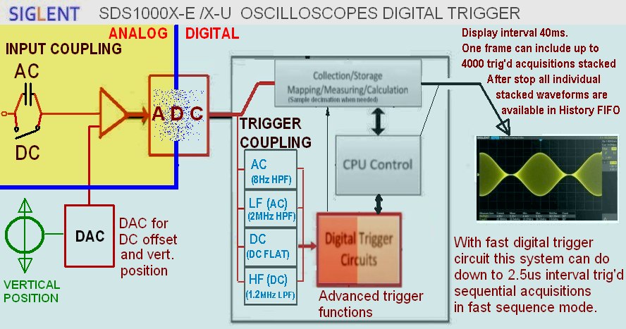
And note, of course trigger engine see sample interval coming samples and its resolution is this but of course this is not at all enough.
There need interpolate between these 2 or 1 ns interval sample points for final positioning. I do not know exactly but example some imagine may give roughly if look how channel skew adjustment resolution is. -
Of course then ADC data is decimated, from 100 raw samples it take only one to acquisition memory and rest it throw away. But in this case peaks can affect and they are not visible because Primary Trig engine is before this decimation!!!
And note, of course trigger engine see sample interval and its resolution is this but of course this is not at all enough.
There need interpolate between these 2 or 1 ns sample points for final positioning.
That's why I asked the OP to increase his sample rate to the full 1GS/s.
How does the trigger do that final interpolation and positioning? Not that it likely matters in this particular case. -
Well, the point of the triggering mechanism is that it should trigger only when all of the conditions you define are actually present. Therein lies the crux of the matter -- I've seen no evidence that all of the conditions really *are* present. Its possible that there's something on the input side of the circuit that is ultimately resulting in the kind of noise spike that would have to be present for the triggering mechanism to fire the way it is, but I haven't gone looking for that. But now that you mention it, I should probably be sampling that on a different channel so I can see if there's anything unusual there.
First, this scope whole trigger system is all after ADC. Trigger engine do not see ANY single thing but just 8 bit data bytes coming from ADC. If in this data stream is not spike or what ever, these can not also affect triggering. Absolutely and infinitely. I know it deeply enough for this claim.
Then please examine the CSVs I uploaded (you'll need 7-zip to open the archives. 7-zip can be retrieved from https://www.7-zip.org), most especially the one named "FAIL1GS-SINGLE-section" which can be downloaded from: https://www.eevblog.com/forum/testgear/siglent-sds1204x-e-released-for-domestic-markets-in-china/?action=dlattach;attach=1124706, and explain how the trigger could possibly have fired when it did given the parameters I used. Note that the contents of the CSV in the archive I linked to are a subset of the entire capture, in particular the 1.5ms worth of capture data leading up to the trigger firing. Since I defined that the first corner of the trigger should be between 1.2 and 1.4ms before the trigger point, with 3.5V as the crossing point for that corner, we clearly should expect to see a voltage less than 3.5V within 100us of that supposed crossing point. But there's nothing anywhere close to that there, or anywhere else within the 1.5ms leading up to the point the trigger fired.
Note that the parameters of that capture were such that the scope was sampling at a full 1GS/s, and the trigger mode was "Normal" (not "Auto"). If the trigger system is using post-ADC data and the data in the capture is not the result of decimation (and it shouldn't be with 1GS/s sampling), then what we see in the capture should be *exactly* what the trigger system sees, no? And yet, I can find no explanation for why the trigger fired on the basis of the data in the capture.
I examined the waveform while the scope was stopped both with interpolation enabled and with it disabled. It made no difference. But most telling is that the *smallest* voltage seen anywhere within 1.5ms prior to the trigger point is 4.33V, which is *well* above the 3.5V threshold I defined for the starting corner of the slope window.
This is why I'm skeptical that the triggering mechanism is behaving properly. If there's noise that is causing the trigger to fire, it is not present in the capture. Either I don't understand how the slope trigger mechanism is supposed to behave, or it has a bug. I see no other options on the table given the data.
By the way, I see the same behavior even with "slow" capture mode.
-
It was and user error was confirmed.kc, I'll do a little exercise with your triangular waveform later in the evening when I've got some real time as the rising Slope trigger is giving unexpected results and we need get to the bottom of this.

Will have something for you to examine come your morning.
Awesome, thanks! Should be interesting.
Slope triggering works as expected if you RTFM !
Expressly this:
The slope trigger looks for a rising or falling transition from one level to another level in greater than or less than a certain amount of time.
P71
https://siglentna.com/wp-content/uploads/dlm_uploads/2020/11/SDS1000X-ESDS1000X-U_UserManual_UM0101E-E05A.pdf
However there is a little trap for the inattentive in that once Levels have been set and then Limit Range (time between levels) the trigger Levels cannot be adjusted without starting from scratch again.
So how to pick a valid Limit Range.....with Cursors or just eyeballing the graticules of course and then all works as expected while the limit range time is met between the Levels.
So a couple of screenshots using the Print button so menus remain visible.
SDS1104X-E SN#0012 so a very early unit. Fresh Default setup and then Ch4 selected as is my preference.
SDG1032X Triangle with offset and symmetry adjusted to approximate kcbrown's waveform.
BNC cable connection.

-
It was and user error was confirmed.kc, I'll do a little exercise with your triangular waveform later in the evening when I've got some real time as the rising Slope trigger is giving unexpected results and we need get to the bottom of this.
Will have something for you to examine come your morning.
Awesome, thanks! Should be interesting.
Slope triggering works as expected if you RTFM !
Expressly this:
The slope trigger looks for a rising or falling transition from one level to another level in greater than or less than a certain amount of time.
P71
https://siglentna.com/wp-content/uploads/dlm_uploads/2020/11/SDS1000X-ESDS1000X-U_UserManual_UM0101E-E05A.pdf
I think the above deserves some additional explanation. The implication of the manual here is that there is absolutely no difference between "rising" and "falling" slope settings. The way I interpreted the slope trigger mode, when used with the [= . =] voltage range definition, is this:- The slope mode allows you to define a range of slopes defined by two points on the voltage versus time curve. The time range defines the range of allowed times for the first transition point. Zero time is the second transition point time, as that's when the trigger fires. The voltage range defines the two voltages through which the waveform must pass in order to fire the trigger.
- With the "rising" slope setting, the lower voltage is the one that's assigned to the time range definition, and the upper one is assigned to the zero time point. Also, with the "rising" slope setting, it seems reasonable that the triggering mechanism must see a rising transition through each point, though I can see how it would still work if it latched on either type of transition. The important thing is the voltage and time location of the two points through which the transition must pass.
- With the "falling" slope setting, the higher voltage is the one that's assigned to the time range definition, and the lower one is assigned to the zero time point. Also, with the "falling" slope setting, it would make the most sense for the triggering mechanism to insist on seeing a falling transition through each point (though again, that's not strictly necessary).
In this way, with the voltage range boundaries defined in that manner, the triggering mechanism would be guaranteed to not fire in "rising" mode unless both of the following are true:- It saw the first transition through the lower voltage.
- It saw the second transition through the upper voltage between the two time boundaries after the first transition.
The end result is that, if it works as described above, you should always see an edge pass through the lower voltage within the defined range of time before the trigger fired, and you should always see an edge pass through the upper voltage at time zero. And frankly, it seems most logical for the transitions to be rising edge only when "rising" is the slope type, and falling edge only when "falling" is the slope type.
Using the numbers I defined for my trigger settings, this means I would expect to see an edge pass through 3.5V at somewhere between -1.4ms and -1.2ms, i.e. 1.2ms to 1.4ms before the trigger fired, and another edge pass through 4.5V at time zero, i.e. when the trigger fires.
But I've seen nothing to indicate any transition at all through 3.5V between 1.2ms and 1.4ms before the trigger fired. This is what I don't understand, and is why I think the trigger mechanism might have a bug.
Put another way, I fail to see how my understanding of the trigger mechanism is incorrect unless the trigger mechanism is defined in such a way as to make "rising" versus "falling" worthless as a distinguishing attribute of the slope trigger type.QuoteHowever there is a little trap for the inattentive in that once Levels have been set and then Limit Range (time between levels) the trigger Levels cannot be adjusted without starting from scratch again.
I noticed that, but didn't make that error for the test runs I performed for this discussion.QuoteSo how to pick a valid Limit Range.....with Cursors or just eyeballing the graticules of course and then all works as expected while the limit range time is met between the Levels.
That's exactly what I did.
-
OK, I did this, and here are the results.
The attached screenshots show the captured waveform in full. One with the mask, and one without.
Also, I've attached the CSV of the data from -1.5ms to 0ms (I had to use 7zip to archive it because zip didn't compress it enough). My analysis of it shows that the minimum voltage seen in that interval is seen at -27 ns, with a value of 4.33V.
Is it perfectly just this screen shot what is also this .CSV.
There can not see exactly what was all important settings just when this happen.
Least I can say this is not trigged from this signal data if your previously told trigger slope etc settings are used and last 1.5ms data before trig time position is what is in CSV.
But for further analyze you need tell exactly what setup was for this screen shot with this CSV. Sad there is not CSV from this part where can assume trigger need happen in just this "sweep".
Btw, are you hunting some nanosecond things from this signal or why you use full BW.
Sidenote. Normal default trigger hysteresis, what is fully hidden from user, is roughly 0.3 div. When user select [noise reject on] no where is displayed inform to user what it do and many may think it is some kind of freq filter. Its (main) function is make this hysteresis "window" more wide. With noise reject on it is roughly 0.8div. And it need also note this hysteresis position depends direction. If we are going up this hysteresis is before aka under threshold level and if we are going down hysteresis is before aka over thresold level and this is also in slope trigger and for both thresholds. So if user example turn noise reject on and he loose trigger it need also check if this invisible Mr.Hysteresis have arrived to room making his magic...
It is good to know but not reason in this case.
-
More Slope trigger tests....some not triggering due to settings used.
Screenshots should speak for themselves.
-
Is it perfectly just this screen shot what is also this .CSV.
There can not see exactly what was all important settings just when this happen.
The trigger settings for the CSV and the screenshot are the same as for all of the others:
Trigger mode: slope
Slope mode: rising
Limit range type: [-- . --] (i.e., the first transition must happen between two time points prior to the trigger point)
Limit range values: 1.20ms to 1.40ms (which I interpret as meaning that the first transition must happen between 1.40ms and 1.20ms before the second transition point happens)
Lower voltage bound: 3.50V
Upper voltage bound: 4.50V
Coupling: DC
Noise rejection: off
The mode and lower and upper voltage bounds are also visible in the screenshot.
The CSV I supplied is a subset of the entire capture seen in the screenshot. While the capture goes from -7ms to +7ms (0ms is of course the point where the trigger fired), the CSV I supplied only goes from -1.5ms to 0ms. I would have uploaded the CSV of the entire capture if this forum allowed uploads that large, but even with 7-zip, the resulting archive is 9 megabytes in size, far too large for uploads here.QuoteLeast I can say this is not trigged from this signal data if your previously told trigger slope etc settings are used and last 1.5ms data before trig time position is what is in CSV.
This signal that you see in the screenshot *did* cause the trigger as I defined it above to fire. That's the point. I see no reason it should have, but it did anyway.QuoteBut for further analyze you need tell exactly what setup was for this screen shot with this CSV. Sad there is not CSV from this part where can assume trigger need happen in just this "sweep".
The CSV starts at 1.5ms before the trigger fired and ends at the point the trigger fired. Given the "rising slope" mode and the settings I used, I expected to see a transition through 3.5V at somewhere between 1.2ms and 1.4ms before the trigger fired. Since the CSV covers from 1.5ms before the trigger fired to the point where the trigger fired, it easily covers the period of time during which I would have expected to see a transition through 3.5V.QuoteBtw, are you hunting some nanosecond things from this signal or why you use full BW.
I used full bandwidth only for the purpose of testing the triggering mechanism. As it's defined, and given the data captured, I see no evidence that the bandwidth itself is the problem, particularly since the capture was running at the full 1GS/s rate (which easily satisfies Nyquist for 200MHz bandwidth), and especially since you said that the trigger mechanism is using the same data out of the ADC that the capture mechanism is using (meaning: if the trigger fired due to a transition, that transition should be present in the capture).QuoteSidenote. Normal default trigger hysteresis, what is fully hidden from user, is roughly 0.3 div.
Well, keep in mind that the lowest voltage seen in the time range of -1.5ms to 0ms before the trigger fired is 4.33V. The capture was taken at 500mV/div. It doesn't sound like 0.3 div of hysteresis is enough to account for that amount of needed voltage swing.QuoteWhen user select [noise reject on] no where is displayed inform to user what it do and many may think it is some kind of freq filter. Its (main) function is make this hysteresis "window" more wide. With noise reject on it is roughly 0.8div. And it need also note this hysteresis position depends direction. If we are going up this hysteresis is before aka under threshold level and if we are going down hysteresis is before aka over thresold level and this is also in slope trigger and for both thresholds. So if user example turn noise reject on and he loose trigger it need also check if this invisible Mr.Hysteresis have arrived to room making his magic...
It is good to know but not reason in this case.
That is definitely good to know, and something I'll try to keep in mind.
Thanks very much for all the incredibly helpful info, by the way. It's a gold mine here ...
-
More Slope trigger tests....some not triggering due to settings used.
Screenshots should speak for themselves.
In each test you're performing, you're using a "<=" type of time definition, meaning the first transition point can occur any time between the defined time and zero before the second transition point.
What happens when you define a time range, i.e. the "[-- . --]" type of time definition? That's what I'm using, and for good reason: I didn't want there to be any possibility of triggering on the falling edge, and I also wanted to ensure that the trigger didn't fire in the event the rising edge was much more steep than what I'm expecting.
-
No look at them again, <=, >= and both rising and falling for each.More Slope trigger tests....some not triggering due to settings used.
Screenshots should speak for themselves.
In each test you're performing, you're using a "<=" type of time definition, meaning the first transition point can occur any time between the defined time and zero before the second transition point.
Haven't tried [-- . --] yet..........and maybe not tonight as it's getting late and needing beauty sleep !
In the next 24hrs I promise.
-
No look at them again, <=, >= and both rising and falling for each.More Slope trigger tests....some not triggering due to settings used.
Screenshots should speak for themselves.
In each test you're performing, you're using a "<=" type of time definition, meaning the first transition point can occur any time between the defined time and zero before the second transition point.
Oh, yep, sure enough. Awesome.QuoteHaven't tried [-- . --] yet..........and maybe not tonight as it's getting late and needing beauty sleep !
In the next 24hrs I promise.
LOL! No worries. Same here, actually. It's 3:30am for me right now! That's okay, because that's my normal schedule (I'm weird that way), but it means I'll have to pick this back up tomorrow.
If there's something in particular you'd like me to try on my end, please let me know.
-
Least I can say this is not trigged from this signal data if your previously told trigger slope etc settings are used and last 1.5ms data before trig time position is what is in CSV.
This signal that you see in the screenshot *did* cause the trigger as I defined it above to fire. That's the point. I see no reason it should have, but it did anyway.
No.
Perhaps some language barrier.
What I mean.
There in .CSV can not find anything what can explain this trig in this place. Btw how you know it is trigged. have you seen trig out signal just for this. So we do not even know if it is trigged or captured without true trig due to example some rare well hidden bug what now pop up in just with all your settings.
Have you tried same with analog side BW reject.
Have you tried it with more wide slope steep. Example 1ms / 2ms. Do it change situation.
Have you tried using Trigger noise reject ON. (more wide hysteresis).
Have you tried using 1x probe (now with 10x probe your real input is 50mV/div) .... oh but you have 4V DC offset...
When it do wrong looks like trig, do it happen always in same time position related to signal, same place in this slow falling edge?
So this signal data, so what can see in this CSV, can not be source for this trig if settings are all as told and if this works as I think it is designed and done.
Also this language barrier make me wonderin this your explabnation about slope trig timing.
Long time ago after when SDS1004X-E was launched I have written quite detailed introduction to these trigger functions, but unfortunately they are all in Finnish language and google can not translate it or result is just total garbage.
When slope rise, first it meet bottom threshold hysteresis bottom threshold level... it may cross over this level many times... but this bottom need be crossed rising direction and after this last rising cross over first time it rise cross over hysteresis upper level what is also same as this trigger type bottom threshold level... after then it start count time. Signal is rising and time go next it cross over upper trig threshold bottom hysteresis threshold and it may cros over it multiple times...up direction down direction until it do not drop and it continue rising... soon it first time cross over upper threshold hysteresis top level what is also same as upper trigger threshold. If time is over minimum but under maximum it generate trigger. Of course this timing can also explain opposite way. Result is same.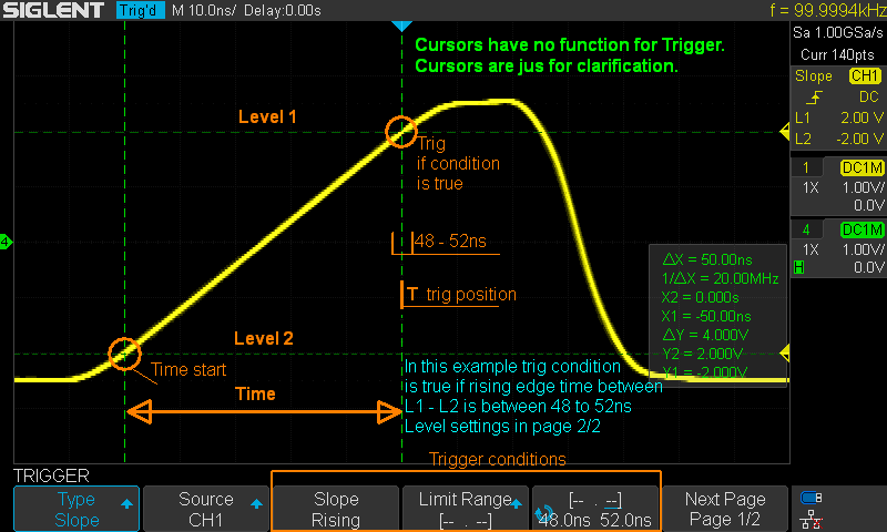
Old image from my trigger guidance material
about hysteresis, of course there need also some explanation what happen in these images bit here these are only for rise knowledge about hysteresis.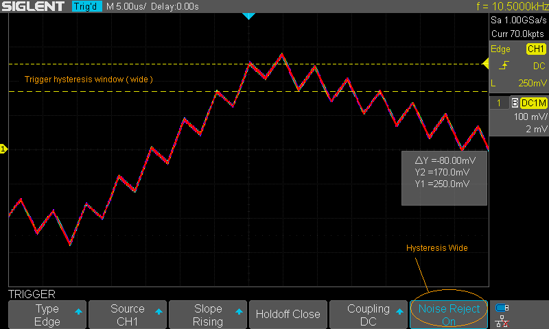
In this case riding signal do not produce trig position jumping... all overlaid single acquisitions hav eperfectly trigged.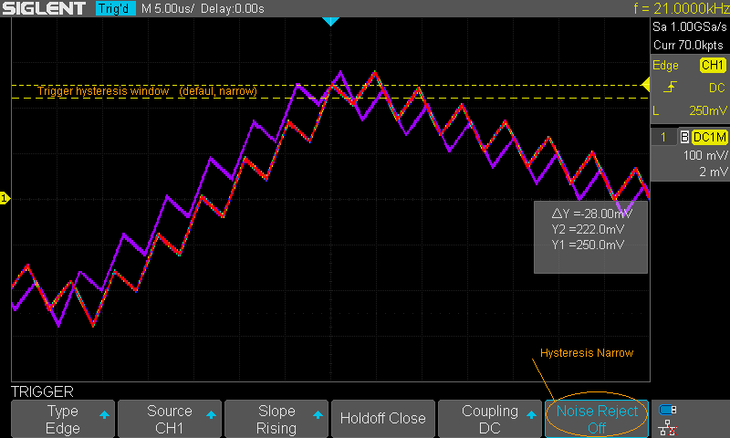
Riding sawtooth produce different triggers because narrow normal hysteresis because its level p-p is higher that hysteresis window. This is of course made for demonstrate this effect. Mostly situation in nature is lot of more complex due do random peaks, noise or ripple etc etc..
And without right crossing hysteresis do not happen ok trig. This hysteresis is is included in both thresholds when trigger mode have two level thresholds.
Also in attached image hysteresis are marked. In this case no need more think hysteresis imho but just for better knowledge who do not know this.
This trig have failed/error due to reason what is unknown at this time.
Still I tiny bit wonder this fat part of trace just before wanted trigger position also its timing is fun...
-
It is explained bit more but unfortunately "scrambled by natural enigma". Our "enigma" is our Finnish language what is said is second difficult after Chinese in world.
In some images there is some english/finglish explanations. But more deep text explanations just with Finnish.
https://siglent.fi/oskilloskooppi-tietoa-sds1004x-e--wfm-speed.html
I am slowly reading through this with help from Google translate. It's very helpful, thank you for writing it!
PS: there is a typo in the second (all yellow) table shown in Figure 1, in the line with t/div= 1ms. Column 6 contains 1G sa/s. It should read 1M sa/s.
-
Least I can say this is not trigged from this signal data if your previously told trigger slope etc settings are used and last 1.5ms data before trig time position is what is in CSV.
This signal that you see in the screenshot *did* cause the trigger as I defined it above to fire. That's the point. I see no reason it should have, but it did anyway.
No.
Perhaps some language barrier.
What I mean.
There in .CSV can not find anything what can explain this trig in this place. Btw how you know it is trigged. have you seen trig out signal just for this. So we do not even know if it is trigged or captured without true trig due to example some rare well hidden bug what now pop up in just with all your settings.
Ah. Yes, I agree, there's nothing in the data that explains why the trigger fired. Rest assured, what was captured *is* the result of the trigger firing. How do I know?- Because I had the trigger operation mode as "normal".
- Because (as you can see from the screenshot), I had the mask operation turned on and set to stop the scope upon violation of the mask, and the capture happens only when the trigger fires when in "normal" mode.
- Because in the CSV you can see that the second condition (passing through 4.5V from below -- well, 4.49V is what the time zero value is. Close enough, especially with sin(x)/x interpolation) *was* met at time zero.
I've posted at least 3 different instances of the issue, along with CSV data to back it up. One of them was in response to Tautech when he suggested I use "single" mode to reproduce the issue. I did, and the end result is the same: the CSV data doesn't show anything to explain why the trigger fired, but the screenshot shows clearly that it did.
At this point, I don't know what other evidence I can supply, but the conclusion from the data is clear: the slope trigger mechanism, at least when using a bracketed time range, is buggy, and will fire when it shouldn't, unless the trigger mechanism is keying off data that is *consistently* failing to land in the capture.QuoteHave you tried same with analog side BW reject.
Limiting the bandwidth helps. I'm running a test now to see if the issue reproduces at all with a 20 MHz bandwidth limit on the input. But limiting the bandwidth shouldn't be necessary. What if you're trying to find high-frequency noise in the signal? The point here is that if noise causes the trigger to fire and the trigger mechanism exclusively uses ADC output, that noise should be present in the capture! But it wasn't, and isn't.QuoteHave you tried it with more wide slope steep. Example 1ms / 2ms. Do it change situation.
Good question. I don't know. I'll have to test that as well. But that said, it's unclear what to expect to gain from it. 200us is plenty of time when the sample rate is 1GS/s. It's not like that time window approaches the limitations of the speed of the scope or anything.QuoteHave you tried using Trigger noise reject ON. (more wide hysteresis).
Yes. It does increase the amount of time to reproduction, but I have seen the issue reproduce even with that in place.QuoteHave you tried using 1x probe (now with 10x probe your real input is 50mV/div) .... oh but you have 4V DC offset...
I've not tried that.QuoteWhen it do wrong looks like trig, do it happen always in same time position related to signal, same place in this slow falling edge?
Looks that way.QuoteSo this signal data, so what can see in this CSV, can not be source for this trig if settings are all as told and if this works as I think it is designed and done.
Agreed.QuoteAlso this language barrier make me wonderin this your explabnation about slope trig timing.
Well, let me try explaining how I think it works a different way.
When you're using the time range option for the slope trigger, what you're really doing is defining a bounding box with a section of the bottom (when using "rising" mode) side of the box that the waveform must pass through and a corner that it must also pass through for the trigger to fire. Like this:
The above shows the trigger configuration I used: a rising slope trigger with a time range of 1.2ms to 1.4ms, a lower voltage of 3.5V, and an upper voltage of 4.5V. The squiggly waveform I've drawn shows a waveform segment that would correctly cause the trigger to fire.
In this case, there are two gates through which the waveform must pass in order for the trigger to fire. The first gate is at T = -1.4ms to -1.2ms (meaning, 1.4ms to 1.2ms before the trigger fires), i.e. anywhere within that range is fine, and the threshold voltage through which the waveform must pass is 3.5V. The second gate is the 4.5V threshold. It must occur between 1.2ms and 1.4ms after the first threshold was passed. If that timing requirement is met at the point the waveform passes through 4.5V, the trigger fires.
Now, it would make the most sense for a rising slope trigger to insist on a rising edge when it passes through the threshold voltages, and I happen to think that such is strictly necessary, because otherwise the trigger could fire on a rising slope that is much greater than that which the trigger conditions specify. What *is* necessary, regardless, is that the waveform pass through the voltages in question while meeting the time requirements for each transition.
Of course, there's an additional requirement: the waveform must never pass below the 3.5V threshold at any time between T = -1.2ms and T = 0. If it does, then that would invalidate the trigger conditions. Another way of stating it is that the *last* time the waveform passes through the 3.5V threshold must be between 1.4ms and 1.2ms prior to the time when it passes through 4.5V.
Maybe the above makes what I've got in mind more clear. If not, I'll do my best to clarify further.
-
Have you tried same with analog side BW reject.
So far this issue has *not* reproduced with the 20MHz bandwidth limiter enabled on the probe. Looks to me like whatever's causing this, it's very high frequency noise that somehow doesn't appear in the capture.
I'll try some of the other things next.