Another happy E4 --> E8 customer here. Thanks Mike and all

Arrived today - 10days after ordering it from Tequipment- Cal date November 12th.
Early Xmas present to myself. Now I just gotta keep my 7 year olds hands off of it....
Inspired by the impressive work of Mike and other forum members I got myself an E4. Before I apply the hack though could anyone shed some light (so to speak) on the attached image? It's a capture from the visible light camera only, in lowish light levels, and shows some horizontal noise bands.
The image was taken before I had charged the battery for the first time and I haven't been able to reproduce it since giving it a charge so the obvious conclusion is that it was something that could be reasonably expected when operating with borderline battery voltage. My concern is that if it does indicate an incipient fault that would require warranty service somewhere down the line I could lose 'hackability'.
Just as another data point,
s/n: 63908xxx
f/w: 1.19.8
cal: Nov 29 2013
The visible camera does get pretty noisy at low light levels - if it looks OK on a good battery I wouldn't worry about it.
The visible camera does get pretty noisy at low light levels - if it looks OK on a good battery I wouldn't worry about it.
Thanks Mike - and thanks for all the work you've done on this
I'm sure you're right - it's clearly a pretty basic camera module. The whole image has obvious noise in low light levels but the lines look more like induced electrical noise to me. I sent the image to FLIR Support to see what they have to say about it and will report back if there are any developments.
Good to know there is a software setting for this. I think you're referring to this post:
https://www.eevblog.com/forum/testgear/flir-e4-thermal-imaging-camera-teardown/msg327178/#msg327178
By "physical setup" you're talking about those calibration steps mentioned in the linked post?
Yes, that's the post - I think it's clear what to do if taking basic trigonometry and the lens-lens-distance in consideraton - one has to align the camera's face-plane geometrically parallel to the reference object plane (ideally a surface with thermal and visual markings/features/borders)
Found time to hook up my E4 to ftp and telnet and adjusted the MSX offset according to your post. Worked great, for a while. Any idea how to make those changes less temporary? Because any auto calibration will reset them to their old values, I tried creating a .rsc in appcore.d/factory.d folders, but to no avail.
What's the difference in using .cfg or .rsc and \FlashBFS or \FlashFS anyway? Looks like FlashBFS contains model dependant firmware and FlashFS per device settings, but when do I have to use which file type in what folder tree to apply some specific settings?
Regarding the banding keithu reported, my visual camera shows horizontal lines and noise as well in low light conditions, thought it to be normal. Maybe it's caused by flickering energy-saving lamps. In a well lit environment I don't see any impairment in image quality, so I didn't care.
Regarding the banding keithu reported, my visual camera shows horizontal lines and noise as well in low light conditions, thought it to be normal. Maybe it's caused by flickering energy-saving lamps. In a well lit environment I don't see any impairment in image quality, so I didn't care.
Interesting that you have the same lines. I also thought they might be caused by fluorescent lighting, but they're just the same under incandescent.
Interesting that you have the same lines. I also thought they might be caused by fluorescent lighting, but they're just the same under incandescent.
Can't really say if they are the same, I just remember to have found some nasty lines in my fusion images, which where caused by MSX adding the noisy visual image to the thermal image.
Here's the word from FLIR Support on the noise lines issue:
It is typical, I'm afraid. I can confirm that we are aware of the problem and it is under investigation.
Interesting response. I just tested my camera and could not reproduce the effect even in a darkened room. My battery is fully charged though so I will test again when its gets towards empty. If it is battery charge related, it would suggest that a buck boost converter output ripple increases at a certain low input voltage level. Maybe it has to work harder to maintain the output and generates the ripple as a result?
I don't think my E4 will be going anywhere near a FLIR service centre anytime soon though

If my unit has this issue, and it annoys me, I will look at filtering the output of the problematic power supply element myself.
Here's the word from FLIR Support on the noise lines issue:
It is typical, I'm afraid. I can confirm that we are aware of the problem and it is under investigation.
My guess is at lower battery voltages, a DC-DC converter is either working harder & producing more noise, or happenning to hit a frequency that coincides with the camera's scan rate.
What's the difference in using .cfg or .rsc and \FlashBFS or \FlashFS anyway? Looks like FlashBFS contains model dependant firmware and FlashFS per device settings, but when do I have to use which file type in what folder tree to apply some specific settings?
FlashFS is all camera-specific, cal data and config files etc.
.rsc are general settings that apply to all models, .cfgs are mostly unit specific ( either due to cal issues or to prevent configs being copied )
I'm not sure there is a direct corresponence between stuff in config files and resources - I think some resources are created/manipulated by the application indrectly from info in the config files.
edit 03.03.2015:
see also: stitching panoramas
https://www.eevblog.com/forum/testgear/flir-e4-thermal-imaging-camera-teardown/msg348715/#msg348715nice sample
https://www.eevblog.com/forum/testgear/flir-e4-thermal-imaging-camera-teardown/msg621514/#msg621514
edit 13.07.2014:
with IM 6.8.9 you must edit the lines inside the php code with gray pipes "gray:-"
see
http://www.imagemagick.org/discourse-server/viewtopic.php?f=3&t=25875&p=113203#p113203
reading radiometric image with Exiftool + ImageMagick (without flir tools)
I extended my php script for reading the embedded png image from Flir E4 in jpg format. Most Flir Cams use 16 Bit RAW as embedded image (like Flir E40).
>php flir.php
usage: flir.php [options] -i ir_file.jpg -o outputimage

Settings:
-i ir_file.jpg      flir radiometric image
-o output.jpg       save  8 Bit image jpg
-o output.png       save 16 Bit image png

Options Summary (type input values without units) :
--resize val        scale sensor size with "convert -resize val" (val i.e. 600x or 100%, default is 200%)
--tref temp         overwrite embedded Reflected Apparent Temperature (degree Celsius)
--tatm temp         overwrite embedded Atmospheric Temperature (degree Celsius)
--dist distance     overwrite embedded Object Distance (m)
--hum humidity      overwrite embedded Relative Humidity (%)
--emis val          overwrite embedded Emissivity (val i.e. 0.95)
--rmin raw_min      set min RAW value instead embedded value (set scale min temp)
--rmax raw_ma       set max RAW value instead embedded value (set scale max temp)
--pal iron.png      use own palette (instead of embedded palette.png)
--clut              disable "Color LookUp Table" and color scale (save a grayscale image)
--scale             disable color scale on the right edge
--stretch           stretch "middle of color scale" to "medium of gray image"
--pip[=AxB]         input image is a flir PiP radiometric image
                    overlay embedded "real image" with "ir image"
                    [optional] crop ir image to size AxB (i.e. --pip=90x90 )
--msx               Flir MSX Mode for PiP
--shade             Flir MSX Mode for PiP with amboss effect
--help              print this help

# source:
# [1] http://u88.n24.queensu.ca/exiftool/forum/index.php/topic,4898.0.html
Edit the path to exiftool and imagemagick !!
let's try with the E4 sample image from here
https://www.eevblog.com/forum/testgear/flir-e4-thermal-imaging-camera-teardown/msg340938/#msg340938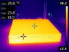
>php flir.php -i FLIR0080.jpg -o test1.jpg

>php flir.php --pip -i FLIR0080.jpg -o test2.jpg

>php flir.php --pip --msx -i FLIR0080.jpg -o test3.jpg

>php flir.php --pip --shade -i FLIR0080.jpg -o test4.jpg

>php flir.php --pal rainBGR.png -i FLIR0080.jpg -o test5.jpg

exiftool FLIR0080.jpg -b -EmbeddedImage > real.jpg
see result images below
background info to used formulas- E4 manual pdf page 57 of 74
- Notice_to_customer_FLIR_Ax5%20I_O_synchronization_and_measurement.pdf (see attachment)
-
http://u88.n24.queensu.ca/exiftool/forum/index.php/topic,4898.msg23944.html#msg23944let's begin:
with tau=1,0 (ignore athmosphere)
U_tot= measured camara sensor voltage
U_tot=eps*U_obj+(1-eps)*U_refl
->   U_obj=(U_tot-(1-eps)*U_ref)/eps
next step (S= measured camara sensor voltage in digits):
I must change the sign of paremeter O, because O is saved negative in exif header of Flir jpg
T (in Kelvin) = B / log(R/(S + O) + F)
-> S = R / exp(B/T-F)-O
now write RAW instead of S
and R_sensor instead of U_tot:
  RAW_refl = R / exp(B / T_refl - F ) - O
  RAW_obj=(RAW_sensor - (1-eps)*R_ref)/eps
  T (in Kelvin) = B / log(R/(RAW_obj + O) + F)
  T (in °C) = B / log(R/(RAW_obj + O) + F) - 237.15
now substitute R with R= R1/R2 compare the formulas with php code:
// calc amount of radiance of reflected objects ( Emissivity < 1 )
$RAWrefl=$R1/($R2*(exp($B/($Temp_ref+273.15))-$F))-$O;

$RAWmaxobj=($RAWmax-(1-$Emissivity)*$RAWrefl)/$Emissivity;

$Temp_max=sprintf("%.1f", $B/log($R1/($R2*($RAWmaxobj+$O))+$F)-273.15);
don't forget that $Temp_ref = ReflectedApparentTemperature ( in °C)
Calculations of Atmosphere transmissivitysee
http://u88.n24.queensu.ca/exiftool/forum/index.php/topic,4898.msg27546.html#msg27546we need
15 parameters for a temperature calculation
$ exiftool -Atm* -Planck* -Object* -Emis* -Reflected* -Relativ* 4x4-100m.jpg
Atmospheric Temperature         : 20.0 C
Atmospheric Trans Alpha 1       : 0.006569
Atmospheric Trans Alpha 2       : 0.012620
Atmospheric Trans Beta 1        : -0.002276
Atmospheric Trans Beta 2        : -0.006670
Atmospheric Trans X             : 1.900000
Planck R1                       : 14168.402
Planck B                        : 1386
Planck F                        : 2.5
Planck O                        : -7363
Planck R2                       : 0.026881648
Object Distance                 : 100.00 m
Emissivity                      : 0.95
Reflected Apparent Temperature  : 30.0 C
Relative Humidity               : 50.0 %
- hint for
windows user for using php as a portable version without some installations:
download from
http://windows.php.net/download/#php-5.4 the current version 5.4.xy
extract zip to a folder php-5.4.xy-nts-Win32-VC9-x86
run > php-5.4.xy-nts-Win32-VC9-x86\php.exe flir.php ... options...
- download
ExifTool from version
9.54- use the
Q16 version of imagemagick !!
changes, enhancements and informations around E4 RAW sensor values
Hi All-
I was registered with this username in the past, but seems it disappeared, maybe I wasn't active enough, not sure, but here I am again...
Anyways, I was wanted a FLIR camera for over a few years now, but cost for the high resolution was just too much. You all got me to pull the trigger on this and I just ordered the E4 through Tequipment using the EEVblog discount (thanks!). I am close to where they ship these from (they ship them out of PA, not NJ where their office is), so I should have it quick. I'll report back on the firmware/calibration date, but I'm guessing I'll be good as the units they are shipping I was told they received last week and I think others reported the hackable firmware version as of last week. I keep my fingers crossed until then...

FlashFS is all camera-specific, cal data and config files etc.
.rsc are general settings that apply to all models, .cfgs are mostly unit specific ( either due to cal issues or to prevent configs being copied )
I'm not sure there is a direct corresponence between stuff in config files and resources - I think some resources are created/manipulated by the application indrectly from info in the config files.
Thanks, so my stuff should go to FlashFS. But I still have to find a way to make my MSX adjustments permanent. I think calibration gets those values from calib.rsc every time and is keeping overwriting mine, but I guess it's a bad idea to do my edits there.
While playing with my backupped files I tried to extract the calibration pic and bad pixel map as mrflibble did in this post:
https://www.eevblog.com/forum/testgear/flir-e4-thermal-imaging-camera-teardown/msg326966/#msg326966Looks like my cam has 62 bad pixels in 54 clusters and my calibration picture doesn't show heavy banding.
FlashFS is all camera-specific, cal data and config files etc.
.rsc are general settings that apply to all models, .cfgs are mostly unit specific ( either due to cal issues or to prevent configs being copied )
I'm not sure there is a direct corresponence between stuff in config files and resources - I think some resources are created/manipulated by the application indrectly from info in the config files.
Thanks, so my stuff should go to FlashFS. But I still have to find a way to make my MSX adjustments permanent. I think calibration gets those values from calib.rsc every time and is keeping overwriting mine, but I guess it's a bad idea to do my edits there.
While playing with my backupped files I tried to extract the calibration pic and bad pixel map as mrflibble did in this post:
https://www.eevblog.com/forum/testgear/flir-e4-thermal-imaging-camera-teardown/msg326966/#msg326966
Looks like my cam has 62 bad pixels in 54 clusters and my calibration picture doesn't show heavy banding.
Remember that (AIUI) all config files in a folder are scanned, in alpjhabetical order so if you find somewhere that a setting appears to be set, you should be able to override it by adding another rsc file with a later alphabetical name. Remember that RSC files need to have a correct CRC32.
Incidentally, in terms of MSX misalignment if you've had the camera out, it is possible that the vis cam isn't seated quite right when clipped back in - I've had this happen.
As the bad pixel map has been mentioned again. Here are my observations from the test I did on my camera....
I set the camera to show bad pixels.
The display showed quite a number....around a 100 or so. That is not great worry to me at all BUT there was some odd stuff that I noted during the test.
1. The dead pixel map was NOT constant. If you captured several images, as I did, you could see that some pixels were always bad, whilst others came and went at random. Almost like twinkling stars !
I immediately thought that this was compression artefacts on the LCD screen. But no, if I open the uncompressed images in FLIR Tools there are definitely differences in the pixel maps captured. Nothing massive but there appear to be quiet a few pixels that appear and disappear.
2. In the dead pixel mode with the lens cover closed, it was possible to see a sort of 'time tunnel' effect with a sweeping cone of noise travelling from the outer edges of the image to the middle, or was it the other way around, I forget. It was an interesting effect, like some sort of video processing algorithm at work.
[Remember that (AIUI) all config files in a folder are scanned, in alpjhabetical order so if you find somewhere that a setting appears to be set, you should be able to override it by adding another rsc file with a later alphabetical name. Remember that RSC files need to have a correct CRC32.
Incidentally, in terms of MSX misalignment if you've had the camera out, it is possible that the vis cam isn't seated quite right when clipped back in - I've had this happen.
I didn't remove the visual camera, still it might got a little shock from dis-/reassemling the device. It's off about 4x1 pixel @2m, but it adds up on greater distances.
I tried a .rsc file with the new parameters, but are those loaded after calibration occurs? Because each auto calibration resets the MSX offset to it's old state. When on a telnet session, you could rset the new values, then it worked for while and after some time calibration kicks in, misaligning MSX and rls showed the old values again.
1. The dead pixel map was NOT constant. If you captured several images, as I did, you could see that some pixels were always bad, whilst others came and went at random. Almost like twinkling stars !
Saw the same on my cam when showing bad pixels with rset. Looked almost like an insect swarm, i.e. changing quite a lot. I captured some images and intend to compare them to the map extracted out of the calibration pic.
Looks like my cam has 62 bad pixels in 54 clusters and my calibration picture doesn't show heavy banding.
Are you sure about the banding? I'm
guessing you may be a bit overly optimistic, but I cannot be sure ofcourse. You did the image processing. Why do I think you might be too optimistic about the banding? Two reasons:
First, the bad pixels in the first image are really dark. So I am guessing you are looking at greyscale stretched values from lowest to highest, without doing something about the raw values of those bad pixels. If you look at my pictures waaay back, then you'll see that the bad pixels are medium grey. That's because I substituted the median value to bad pixels. That way they do not mess up the normalization.
And second, you
do get correction terms that have banding in it. That alone tells me that there is correction being done for banding in the underlying raw values.
If you're interested you could PM me your two files for calibration + correction, so I can run it over here as well as a comparison. That, and it gives me an excuse to improve the bit of code I have to process cal + correction images. Right now it's crap.
 Edit:
Edit: Oh yeah, and third reason I think you really get more banding is that your first pic doesn't show enough vignetting. You could be lucky and get a really good sensor with almost no banding. However getting a magic lens that doesn't show roughly the same amount of vignetting as on my pics would seem unlikely.
Looks like my cam has 62 bad pixels in 54 clusters and my calibration picture doesn't show heavy banding.
Are you sure about the banding? I'm guessing you may be a bit overly optimistic, but I cannot be sure ofcourse. You did the image processing. Why do I think you might be too optimistic about the banding? Two reasons:
First, the bad pixels in the first image are really dark. So I am guessing you are looking at greyscale stretched values from lowest to highest, without doing something about the raw values of those bad pixels. If you look at my pictures waaay back, then you'll see that the bad pixels are medium grey. That's because I substituted the median value to bad pixels. That way they do not mess up the normalization.
And second, you do get correction terms that have banding in it. That alone tells me that there is correction being done for banding in the underlying raw values.
If you're interested you could PM me your two files for calibration + correction, so I can run it over here as well as a comparison. That, and it gives me an excuse to improve the bit of code I have to process cal + correction images. Right now it's crap.
Edit: Oh yeah, and third reason I think you really get more banding is that your first pic doesn't show enough vignetting. You could be lucky and get a really good sensor with almost no banding. However getting a magic lens that doesn't show roughly the same amount of vignetting as on my pics would seem unlikely.
Of course you're right, it's highly unlikely I did the calculations the way you did, so our images aren't comparable. For instance, I replaced all bad pixels (i.e. pixels with a value way off the others) by zero and ignored them while normalizing. Besides them, my smallest value was 31863 and my highest was 46430, which mark the range from 0 (black) to 1 (white) in the shown image. But I didn't think of it much, so possibly all my math is fubar.
And I do have banding in my thermal images, at least it's noticable on uniformely heated areas. As you said, my 3rd picture doesn't look as nice as the first one. So I'm not that lucky, I was just interested to see those pics and thought someone else might be as well (regarding binning, etc.). Of course you can have my calibration data and apply the same math to them as you did on yours.
>php flir.php --pip --msx -i FLIR0080.jpg -o test3.jpg
Hey tomas123 - love the work your doing with this flir.php! Do you think there would be a way to use the --msx without the --pip? (combine the 640x480 real image at 1x with the 320x240 thermal at 2x)
Trying to get the nicest looking images I can out of it without clutter of the scale bar or other UI elements.
Did someone encoutered issue - when Flir E4 camera is connected to PC it is unable to boot?
I would like to aks is is possible to modify the camera settings to set the black background to some transparency level?
Slightly OT - is that a WRAP or ALIX? (pFsence? m0n0wall?)
Do you think there would be a way to use the --msx without the --pip? (combine the 640x480 real image at 1x with the 320x240 thermal at 2x)
Trying to get the nicest looking images I can out of it without clutter of the scale bar or other UI elements.
php is only a wrapper for the two command line tools exiftool and convert
read the code and use convert it as desired
php is only a wrapper for the two command line tools exiftool and convert
read the code and use convert it as desired
Your resulting images are indeed pretty neat! Yesterday I made the same non-linear function + some other stuff in python, and that's looking good. Do you happen to have some functions for inclusion of atmospheric influence? I've got reflection, but might as well include some functions for atmospheric influence while I'm at it.
Oh yeah, and you had some interesting typo somewhere that had me scratching my head for a bit. R=R1/R2. Not R1=R/R2.
Obvious in hindsight, but not when you're trying to figure things out from fragmented information.
Oh yeah, and you had some interesting typo somewhere that had me scratching my head for a bit. R=R1/R2. Not R1=R/R2
wow, you are right and you are the first power reader of my post
http://u88.n24.queensu.ca/exiftool/forum/index.php/topic,4898.msg23944.html#msg23944it was a hard way, to find the exif tags AND the correlate formula ( scratching my head )
Flir don't public some background informations
Temperature (in Kelvin) = B / log(R / (S - O) + F)
S is the 14-bit digital signal value.
log(x) is the base-e logarithm of the x parameter.
R Planck R constant ( R=R1/R2 )
B Value range 1300 - 1600.
F Value range 0.5 - 2
O (offset) constant
with R1/R2 Flir avoids large values and rounding errors
Do you happen to have some functions for inclusion of atmospheric influence?
I haven't found any practical informations for air calculations
I wrote here
http://u88.n24.queensu.ca/exiftool/forum/index.php/topic,4898.msg24310.html#msg24310extend the formula for "ObjectDistance, RelativeHumidity, Atmospheric Temperature" is not simple
read a fluke manual of Ti100, Ti105, Ti110, Ti125 - there is also no compensation of air influence
here you find more informations (a sample with 100m (!) distance):
http://qirt.gel.ulaval.ca/archives/qirt2010/papers/QIRT%202010-092.pdf
from the book "Infrared Thermography Errors and Uncertainties" (google for preview, page 55 ff)
simple ignore the inclusion of atmospheric influence in near distances,
measuring error is minor versus reflections (see link to pdf and google books)
at page 57 you find this formula with air influence

s is the signal level (14/16 Bit from sensor) and proportional to the radiation intensity
now I know, why Fluke ignores the atmospheric influence
.caps.config.image.targetNoise.enabled bool true
.caps.config.image.targetNoise.targetNoiseMk int32 135
It could actually be noise reduction or shaping - maybe this is a threshold to decide when to apply noise reduction, i.e. adjust filter until noise is below the target value. "Mk" - mask? Perhaps something like a hysteresis function?
targetNoiseMk is a noise generator in mK (conforming with NETD/ thermal sensity in Flir Datasheets of the selected cam)
Formerly I stacked some noisy images with Registax or AviStax to subtract out the randomly noise and it works great!!
after setting targetNoiseMk to zero, stacking of images don't improve results

here a sample from a Flir E40 (old cam hacked formerly from 160x120 to 320x240)
in service menu I can measuring the noise
rset .caps.config.image.targetNoise.targetNoiseMk  60 (MilliKelvin)

 Temporal noise        MilliKelvin      Digital Units
Pixel Noise      61.28      12.13
Row Noise        14.84      2.94
Column Noise     13.67      2.71

Spatial noise        MilliKelvin      Digital Units
Pixel Noise      25.69      5.09
Row Noise         7.08      1.40
Column Noise      7.82      1.55
Uniformity      198.23     39.25

Total noise        MilliKelvin      Digital Units
Pixel Noise       67.01     13.27
Row Noise          9.71      1.92
Column Noise      10.10      2.00
and now without noise (cam temperature is 25 Grad):
rset .caps.config.image.targetNoise.targetNoiseMk  0 (MilliKelvin)

 Temporal noise        MilliKelvin      Digital Units
Pixel Noise      19.85      3.93
Row Noise         6.39      1.26
Column Noise      8.64      1.71

Spatial noise        MilliKelvin      Digital Units
Pixel Noise      18.98      3.76
Row Noise         4.70      0.93
Column Noise      5.54      1.10
Uniformity      210.23      41.63

Total noise        MilliKelvin      Digital Units
Pixel Noise      28.96      5.73
Row Noise         5.76      1.14
Column Noise      7.66      1.52
see the differences (NETD is 0,03 °C @ 25°C)
http://gs.flir.com/surveillance-products/surveillance-technology/imaging-technotes/IR_Technology_Parameters
Uncooled infrared cameras systems are typically a little noisier, in the range of 30 - 120mK. Noise in an image can be spatial or temporal.
Spatial noise is noise across the image at any given point in time. It is perceived as an unchanging fixed pattern on top of the image.
Temporal noise is noise at any point in the image over time. It is perceived as the static that moves in an image.
NETD is typically the measure of both these noise types.
remarkably Flir dont't disable the noise generator at the top cams of a serie (Flir E4 -> E8 , Flir E30 -> E60)
This issue of noise still interests me. I have heard from others on this forum that noise is sometimes deliberately introduced to aid digital signal processing. I had not heard of that before but was aware that two of the challenges in uncooled micro-bolometers was taming the output drift and the noise that the detector creates. If the added noise is the same throughout a range of cameras, from cheap to expensive models, it certainly suggests that it is not another form of hobbling...... or is it. I have no idea, but I would welcome some clarity on the subject if anyone understands its purpose in the system.