Nothing more worst than bought a set of Keithley high resistance resistor and then looking for a 6517

Still working & trying to get solid baselines for these REF Resistors
I have 3456A waiting for a spare Transformer. If you see anytime that please inform me 
Looks like that is not so uncommon after all. One of my 3456A's also has a bad transformer.

And none can donate one to the other.
[This is where I am with my catching up - likely I won't succeed doing so]
Returning to a sad little thing sitting on my shelf....
here is the defunct HP6177B current source again - this time with photographic evidence.
I DID comb the known repositories for T&M manuals and came up with ONE (KO4BB if i remember correctly)
but as you can see, it is for another device!
my serial number is 1149A01036, the manual applies to 9C0191...02. There IS a change page, but without
part's location, finding the problem is quite tedious. While there is info on a change page pertaining to Q25, which states that it is now mounted on the heatsink, mine is obviously a newer PCB. I don' want it to be a major research project, so can anyone help here?
My best educated guess... given general design principles, and looking at what's missing... would be that the function of Q25 (I'm guessing a base driver for Q29 or Q30?) in your circuit is either handled by a transistor hidden under Q30 on the same heat sink, or that it is the TO-5 device with the huge round sink in the middle of the board. Very likely if it is a PNP device.
You'll probably have to remove the sink to get a part number by working a screwdriver into the slot from the edge; this is most safely done with the transistor out of circuit, as it is very easy to break legs or traces trying to pry on that kind of sink. I wouldn't be surprised if you find horrible ring cracks when you go to remove that transistor, though... they seem to go hand-in-hand with those big unsupported heat sinks. And obviously, once removed, the first thing to do would be to run it across a curve tracer/junction test.
That's my prime surmise, looking at your problem from the other side of a computer screen over my morning cuppa.

mnem

Possible.
I'd buzz it out and see if you can work out what it's hooked up to directly. If it's a base driver, you should be able to work out what for.
Those TO-5 / TO-39 packages with a massive hat on the like that can shift 5-8W quite happily which is more than a badly mounted TO-66 like the old Q25. If you look at the output stage on all of HP's kit, right up to the 33120A it's got the same type of transistor and heatsink. There are usually plastic discs underneath which absorb any nasty knocks. I had a job once of putting those on and stuffing the boards ... only because I passed the idiot test:

Anyway 33120A pr0n

(stolen from:
https://www.eevblog.com/forum/reviews/hp-33120a-teardown/ )
this is no enjoy..
my spm-11 shortet in the display. (ERO Tantal is really bad, searching and replace)
the pink desaster
In Other News...-group-therapy-thread/?action=dlattach;attach=643907;image)
I'm at the point in my PC case modding project where I have to swap the MB into the new case to continue. Old/crunky HP case is gonna go bye-bye, and I'll be incommunicado for a few hours or days or until I give up and drag out the old laptop.
Cheers!
mnem
ow.
That looks about as far as I ever got through a custom PC build before getting bored

After fumbling my way through a full compensation the other day on a Tek 7A16A plug-in I decided today I was up for more punishment with 2 other plug-ins where I wasn't happy with their compensation. A 7A15A and a AM-6565/U (Military 7A15). So I set them up and was prepared for a long and frustrating haul. Well this old gray beard taking educated shots in the dark discovered a method which
in less than 10 minutes the attenuators were fully and correctly compensated. And this procedure can be applied to other Tek scopes such as the 465/475 with similar attenuator decks.
Being the grouchy old fart that I am there's no way I'm sharing what I discovered. I'm taking it to my grave.
 J/K. If someone is interested I'll post it up.
Do share!
I got some info from the hp/agilent/keysight group on repairing attenuators...think I'll give it a try. First to find the o-rings I need.
Probably the same method I use: twiddle the caps until it sucks the least

I’ve got a whole pile of bits here to build a decent pulse generator both Jim Williams avalanche style and LVC logic style. Really need to finish that and attack this 475A once I’ve sorted the timebase out.
Probably the same method I use: twiddle the caps until it sucks the least
Nope. I'm talking
SQUARE edges and damn near perfect
FLAT TOPS. No compromise. No bullshit. The bees knees.

I am stoked.

Being the grouchy old fart that I am there's no way I'm sharing what I discovered. I'm taking it to my grave.
J/K. If someone is interested I'll post it up.
That is so unlike you, grouchy old fart
mnem, that big copper cooler fan would be almost completely quiet in even the worst Texas suck, right ?
Do share!
I got some info from the hp/agilent/keysight group on repairing attenuators...think I'll give it a try. First to find the o-rings I need.
Promise, I'll post it up later.
@mnem, what is the advantage in having your cabling sleeved? Personally I don't get it apart from the appearance and that said, I spend my time looking at the monitor and not the PC. All I'm really worried about is keeping the airflow through my PC as unrestricted as I possibly can.
mnem, that big copper cooler fan would be almost completely quiet in even the worst Texas suck, right ?
Yup. There's a reason I haven't given it up in almost a decade.
@mnem, what is the advantage in having your cabling sleeved? Personally I don't get it apart from the appearance and that said, I spend my time looking at the monitor and not the PC. All I'm really worried about is keeping the airflow through my PC as unrestricted as I possibly can.
Sleeved cabling became popular with "Tweakers" and the "OC Crowd" because the look and because it provides chafe-resistance for people who are constantly fucking around with their build. As a result, it is now the de facto "standard" for high-end PSUs.
Oh, and quite honestly, because it has been marketed by PSU manufacturers because it is cheap as hell to implement in mass production; you can use the cheapest vinyl-clad tin-plated wires and still make a PSU "Upscale" and color-coordinated by adding a dime's worth of PET braiding.
 https://youtu.be/HkB-GNEt9Fk
Right now the hot ticket is custom-length individually sleeved FAT wires for modular power supplies. As in each conductor in your 6-8 pin GPU wiring and your MB wiring has its own extra fat (usually still 18ga, but fat so it looks mo' bettah) sleeved wire, and then THOSE are organized with wire looms so they look like spark plug wires on a street rod. There is a whole industry around this shit; it's insane. We're talking about people spending a couple hundred or more for a fully modular power supply, then ANOTHER $300-400 for these fucking cables.

For me, it's probably more nostalgia than anything; I used to be in the "Case Modder" crowd back when it was just guys in their garages with Dremels and maybe evening access to a high-school machine shop putting windows and LED lighting and such inside to "glam it up".
So yeah, I "get" sleeving to tidy up; but I don't mind the occasional "snake swallowed a rat" lump if that's the price of getting everything where I want it to be.
mnem
*POIT!*
Returning to a sad little thing sitting on my shelf....
here is the defunct HP6177B current source again - this time with photographic evidence.
It looks somewhat similar inside to the 6181B that I brought back to life about a year ago - I really like this unit, but the schematic is mind-bending the way it is drawn. Mine had multiple issues...
Maybe the schematic for 6181B is close enough?
What's actually wrong with the one you have?
That time when you tried to clean out some stuff from the junk box and had it backfire because the recipient sent you a larger volume of 'stuff'.
Thanks Tautech I think? The Boomerang bag is most apt
You think you have enough diodes there chief?
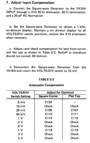
As promised I'll describe the easy procedure I found for adjusting the attenuators quickly and easily. Let me first explain how these attenuator assemblies work and then the procedure.
Attached is a typical attenuator adjustment. This one is from the 7A16A and with some variations they are basically the same on many Tek plug-ins and scopes. The 5mV range does NOT go through the attenuator blocks and it's a direct link from input to the first stage of the vertical amplifier. Typically that cap (C134) does NOT need to be adjusted unless it's been burnt out or someone monkeyed with it. The 10mV and .1V ranges are in the same path between input and first vertical stage. Same with 20mV and .2V ranges, 50mV and .5V ranges. The 1V range and above on a separate range. If you follow the adjustment table sequentially as shown I guarantee you'll spend a frustrating hour or more trying to get the 1KHz square to look decent across all ranges. And you'll still have some waveforms that look like crap. But I figured out the secret and I'll bet the gray beards at the factory used this method and didn't want anyone on the outside to know.
Let's take the 10mV adjustment as an example. An as I mentioned the .1V range is in the same path. So whatever adjustments you make to 10mV range it will affect the .1V range. And this is where it will drive you nuts because if you get one to look good the other doesn't. Back to the 10mV adjustment. The table says simply to “check”. That's a load of garbage. Adjust C114 for square corner but do NOT touch C115. Switch to .1V and adjust waveform for 6 divisions. It will look terrible. Adjust C115 flat top for best waveform. Do NOT adjust C114. Go back to 10mV and it may or may not need a minor tweak of C114. Go back to .1V and check and you are DONE with that range. The waveform should be perfect. Follow the same procedure with 20mV/.2V ranges and 50mV/.5V ranges. Adjust the square corner cap ONLY on the mV range and the flat top cap ONLY on the V range. The 1V range you can adjust both and it should be OK. That's it. 10 minutes and the compensation is done.
I applied this procedure to the 7A15A plug-in which I had to rip apart and remove the attenuator blocks because I had disassemble the switch assembly to clean noisy contacts. So the compensation was way off upon reassembly. In 10 minutes back to perfect. Touched up a military 7A15 with same results. And I went back to the 7A16A that I adjusted the other day but I wasn't happy with the results. It's now perfect. This post is getting a little long so I'll end it here. Later I'll post some waveforms to prove that I'm not giving you guys a line of bullshit.
You think you have enough diodes there chief?
It's ok I said the special magic words "Diodeius Absorbo" and they assimilated into the diode and rectifier box for future use. I was a Scout once upon a time and 'Be Prepared' is a must when your nearest electronics shop is over 3 hours away


 OTOH; pretty much every IT job I've ever worked, my "bench PC" ALWAYS looked like that.
 Ifni save me; now I have this overwhelming urge to sleeve the cabling on my modular PSU too, so all the sleeving matches.
