-
I do too... but haven't been able to lay paws on a decent seeded rye or pump with any actual flavor since before Obama...Huh... according to the relevant wiki, Ciabatta is a modern (80s) invention... created in response to the popularity of baguettes.
Meh!--- I like a good old German Rye slathered with liverwurst, then covered with sweet gherkins!
Ummmmm... FAIL!
Don't get me wrong... I like a juicy grilled steak & onion with a nice aged Parmesan on Ciabatta... but as a substitute for baguettes, especially with wine & cheese or with my coffee...? That's like bringing a salami to a gunfight.
mnem
Just say no to crappy baguette.
Trouble is, that back in the day, everybody produced it, but it has gone out of fashion in Oz.
mnem
*breaditarian-dwagon* -
I have a repair question.
I am trying to repair a programmer module from the 80ies. German manufacturer Kontron. I am struggeling with a totally undocumented (besides operation) stack of two multilayer boards that does not work as expected. The firmware emits errors on start. That board worked long ago but stopped quite some time ago, now I am trying to revive it. I am reverse engineering parts of its schematics (which is a PITA, as I found after a while that some ground connections of the bottom board are made through the upper board, so you will not find them with the lower board only).
Currently I have found two parts that *seem* to be resistors, but that does not make a lot of sense in that position *and* the colour code would not match. On the same board there are 1k resistors with the usual marking brown-black-red-gold.
See the photo attached, the red circled "resistors" marked brown-black-gold-gold measures as 1k (colour code would mean 0.1Ohm), the yellow circled one too (which is expected). There are *two* of those strange parts on the board. Any hints?
One of the "resistors" is from a positive supply voltage (28V) to the upper board, feeding two LM339 and 7 custom hybrids. I am measuring about 8V, so the current should be abt. 20mA. The voltage is not stable, so I doubt this is intended. Using normal colour code I would get a resistance of 0.1Ohm, but I will not feed the 28V directly to the board, possibly frying all the hybrids made of pure unobtainium.
-
As opposed to Reverse Polish Cowgirl, which is when the sheep is on top.I've always thought of "Reverse Polish" as referring to what you do when you take your freshly waxed car down salt-encrusted winter roads.
No, that's Reverse polish.
mnem
yes, you may touch it. -
Inductor? Maybe remove one and pop it on the cheap Chinese component tester?...One of the "resistors" is from a positive supply voltage (28V) to the upper board, feeding two LM339 and 7 custom hybrids. I am measuring about 8V, so the current should be abt. 20mA. The voltage is not stable, so I doubt this is intended. Using normal colour code I would get a resistance of 0.1Ohm, but I will not feed the 28V directly to the board, possibly frying all the hybrids made of pure unobtainium.
mnem

-
I've always thought of "Reverse Polish" as referring to what you do when you take your freshly waxed car down salt-encrusted winter roads.
No, that's Reverse polish.
Given the apparently arbitrary use of capitalisation and punctuation these days, I feel justified in my attribution.
Just spent several amusing minutes on the phone to customer services of "An Supermarket" to report the presence of unordered and unbilled potato crisps (chips if you're a colonial) in my grocery delivery.
Yes, I am that guy. -
Currently I have found two parts that *seem* to be resistors, but that does not make a lot of sense in that position *and* the colour code would not match. On the same board there are 1k resistors with the usual marking brown-black-red-gold.
See the photo attached, the red circled "resistors" marked brown-black-gold-gold measures as 1k (colour code would mean 0.1Ohm), the yellow circled one too (which is expected). There are *two* of those strange parts on the board. Any hints?
Inductor? Which would make it 1uH 5%. However, I would not expect the series resistance to be anything like 1k for a typical inductor*. I'd want to see a decent chunk of the schematic drawn out before I wanted to make any informed guesses about what the components were when they were first put on the board.
*A qualification here. Sticking significant inductance into the DUT of some multimeter's resistance ranges makes them unstable and they give nonsense results, often wandering all over the place (which at least gives a clue as to what's going on). It's the ones that give a rock steady but totally wrong result that are a bastard. -
Inductor? Which would make it 1uH 5%. However, I would not expect the series resistance to be anything like 1k for a typical inductor*. I'd want to see a decent chunk of the schematic drawn out before I wanted to make any informed guesses about what the components were when they were first put on the board.
Yes, could be an inductor. I have not found any more inductors on both boards. Haven't drawn out enough yet. The beast has 4 isolated and 2 more ground referenced voltages that are regulated and switched to the DUT and additionally +5V and +12V for its own processor system... Any error in the digital could cause havoc on the psu part too, I suppose.
Overview of upper und lower boards.
-
Inductor? Maybe remove one and pop it on the cheap Chinese component tester?
mnem
I've come across boards before where inductors the same size & color as 1/4W resistors, got changed for resistors.
And this is the TEA thread, shouldn't we be using something better than a cheap component tester?
David
-
I have a repair question.
I am trying to repair a programmer module from the 80ies. German manufacturer Kontron. I am struggeling with a totally undocumented (besides operation) stack of two multilayer boards that does not work as expected. The firmware emits errors on start. That board worked long ago but stopped quite some time ago, now I am trying to revive it. I am reverse engineering parts of its schematics (which is a PITA, as I found after a while that some ground connections of the bottom board are made through the upper board, so you will not find them with the lower board only).
Currently I have found two parts that *seem* to be resistors, but that does not make a lot of sense in that position *and* the colour code would not match. On the same board there are 1k resistors with the usual marking brown-black-red-gold.
See the photo attached, the red circled "resistors" marked brown-black-gold-gold measures as 1k (colour code would mean 0.1Ohm), the yellow circled one too (which is expected). There are *two* of those strange parts on the board. Any hints?
One of the "resistors" is from a positive supply voltage (28V) to the upper board, feeding two LM339 and 7 custom hybrids. I am measuring about 8V, so the current should be abt. 20mA. The voltage is not stable, so I doubt this is intended. Using normal colour code I would get a resistance of 0.1Ohm, but I will not feed the 28V directly to the board, possibly frying all the hybrids made of pure unobtainium.
My guess: inductors or very low value resistors, but I tend to inductors.
Why?
Look at the traces. There are thick and thin ones. Thick traces are carrying usually
higher currents so the inductors are here for decoupling the current spikes of the digital logic stuff.
I cannot imagine, why there should be low valued resistors. For what purpose? Measuring currents?
If I had to bet on anything, my packet of gummibears would go on the inductors. -
Yep.I have a repair question.
I am trying to repair a programmer module from the 80ies. German manufacturer Kontron. I am struggeling with a totally undocumented (besides operation) stack of two multilayer boards that does not work as expected. The firmware emits errors on start. That board worked long ago but stopped quite some time ago, now I am trying to revive it. I am reverse engineering parts of its schematics (which is a PITA, as I found after a while that some ground connections of the bottom board are made through the upper board, so you will not find them with the lower board only).
Currently I have found two parts that *seem* to be resistors, but that does not make a lot of sense in that position *and* the colour code would not match. On the same board there are 1k resistors with the usual marking brown-black-red-gold.
See the photo attached, the red circled "resistors" marked brown-black-gold-gold measures as 1k (colour code would mean 0.1Ohm), the yellow circled one too (which is expected). There are *two* of those strange parts on the board. Any hints?
One of the "resistors" is from a positive supply voltage (28V) to the upper board, feeding two LM339 and 7 custom hybrids. I am measuring about 8V, so the current should be abt. 20mA. The voltage is not stable, so I doubt this is intended. Using normal colour code I would get a resistance of 0.1Ohm, but I will not feed the 28V directly to the board, possibly frying all the hybrids made of pure unobtainium.
My guess: inductors or very low value resistors, but I tend to inductors.
Why?
Look at the traces. There are thick and thin ones. Thick traces are carrying usually
higher currents so the inductors are here for decoupling the current spikes of the digital logic stuff.
I cannot imagine, why there should be low valued resistors. For what purpose? Measuring currents?
If I had to bet on anything, my packet of gummibears would go on the inductors.
These conundrums are exactly why I got a good (read expensive) set of SMD tweezers a decade ago where in Auto mode they'll happily distinguish between an L and R and give you the dominant reading. Saved my arse a few times.
-
I will add my supernumery 2-penneth and concur; inductors.
-
My guess: inductors or very low value resistors, but I tend to inductors.
Why?
Look at the traces. There are thick and thin ones. Thick traces are carrying usually
higher currents so the inductors are here for decoupling the current spikes of the digital logic stuff.
I cannot imagine, why there should be low valued resistors. For what purpose? Measuring currents?
If I had to bet on anything, my packet of gummibears would go on the inductors.
Yes, inductors would make sense. So I guess they are both toast and the remaining charcoal is carrying the current. I am guessing about that small value, as there is only a transformer secondary, a bridge rectifier and a crapacitor involved (I omit a series tranny used to switch off the supply to the module) in front of the series inductor.
More poking around...
OK, 100R across one of the inductors just let the magic smoke out... So now I will try to power up the remaining and feeding it with a current limited lab supply. -
So...
Fluke 5101B calibrator. Seems to work "erwandfrei" but it may have missed the 180-day calibration period once or twice. What do you guys think? Sell as is? Attempt to calibrate so it agrees with my 34401?
Or secret option #3: buy a new 6 1/2 DMM so it's a bit better. Off course, in that case I should buy at least two or three because that would be the sane thing to do in case one deviates.
-
Discord is up, with the usual suspects...
-
INDUCTORS !!!
I don't know, every body says inductors, so why not me ?!
Thanks for your feedback on the tape label printer thingies. So looks like the most important advice is to run away from "direct thermal" that like shitty thermal printed receipts at the super market, and favour "thermal transfer", as in "laser printer toner transfer". More durable.
Looks like according to the Dwagon, there are indeed some printer with a USB port to let you download your own custom graphics/icons... will try to find one that does that, but will only consider sub 50 Euros printers...
I looked at a few for sale online here, and it seems they ALL use NON rechargeable batteries ?!
So since it gets used infrequently usually... batteries are self discharged by the time you dig out the printer... so you need to buy new batteries every time you want to use it, pretty much... how economical and eco-friendly In this day and age they can't just use a Li-on battery charged via USB port like everybody else ?!
They are not expensive... not as cheap as Dwagon's 12 bucks Brother, but I see a brother at 16 Euros, and then it jumps to about 35 Euros for both Brother and Dymo.
Looks like every printer uses a different tape format / standard ! How practical...
Some printer can use different sizes of tapes. Standard width are not standard... every model of tape has its own standard width...
Anyway, I think the best thing to do is to go direct to the corporate website of Brother and Dymo, to see an exhaustive list of what they currently sell, and check specs carefully. ... hoping I will find one thatfeetsfits my requirements / wishes. Hell they are so affordable, even if I get it wrong, it's not the end of the world... it will still make label, and if it's really too horrible I can sell it half price and go get another one...
Hell might even try to see if I can find a used one locally for a tenner or less !
I have already filled half of the 50 drawers of the largest of the two units...
This evening I will try to see if I can fit all my electrolytic caps in the smaller drawer unit. I already sorted them back in the day, in 3 plastic boxes old man gave. The bins in them are of the least practical shape and depth, well at east the first two of them, so I am glad I am transferring them to easier to use drawers. On the far right is a more recent box, full of caps that need to be sorted. Weighted it at 1325 grams ! So lots of caps... OK, the plastic box has mass... subtract 125 grams at most.. I am still left with 1.2kg worth of caps to sort ! 
So wish me luck !
If I want a chance to fit it all in the drawer unit, I think I will first need to throw some of the caps away... am thinking of the very low value ones, the sub uF ones. They use up 5 bins, yet only a handful of tiny caps to report. sub uF stuff can easily be replaced with film caps these days so... out with those caps. Hey presto, need 5 less drawers now...
@Cerebus : vinyl sticker on project box looks nice... TOO BAD this misplaced screw in the middle ruins the resistor symbol, was so close to perfection !
-
INDUCTORS !!!
I don't know, every body says inductors, so why not me ?!
Thanks for your feedback on the tape label printer thingies. So looks like the most important advice is to run away from "direct thermal" that like shitty thermal printed receipts at the super market, and favour "thermal transfer", as in "laser printer toner transfer". More durable.
Looks like according to the Dwagon, there are indeed some printer with a USB port to let you download your own custom graphics/icons... will try to find one that does that, but will only consider sub 50 Euros printers...
I looked at a few for sale online here, and it seems they ALL use NON rechargeable batteries ?!
So since it gets used infrequently usually... batteries are self discharged by the time you dig out the printer... so you need to buy new batteries every time you want to use it, pretty much... how economical and eco-friendly In this day and age they can't just use a Li-on battery charged via USB port like everybody else ?!
Someone on the UKVRR radio forum bought a Brother P-Touch H101GB recently, it was sold as battery only, but on opening it they found a DC barrel socket was already fitted, but the casing design had been modified to blank off the connector. They said the barrel socket was centre negative, but check just in case.
Unfortunately the thread is in the modern tech section and hidden for non-members with less than 10 posts, so a web link would be pointless.
David
-
I'll bring the beer and a big chunk of pig. (I know the way to a German boy's heart.
What...you'll take British beer to a German boy are you crazy or what? German beer is among the world's finest, they have purity laws over there for their beers )
)
I'm not carrying beer (or half a pig) all that way when they've got perfectly good local stuff. Not that all German beer is great, it's quite possible to get a Maß of insipid, national brewery beer in Germany, just like you can here. "Bitte ein Bit?" - nein danke. Thankfully, the Germans have been a bit more insistent than us in keeping their local breweries alive and kicking and generally if you drink what's brewed locally you can't go wrong.
I could never abide "Lowenbrau", although others loved it.
My favorite German beer is Dortmunder Actien Brauerei, DAB. My dearly departed German/Polish brother in law turned me on to DAB many years ago on tap at a German gun club we used to go to in New Jersey. Sadly, I gave up alcohol when I was diagnosed type 2 diabetic. It has been long enough that I no longer miss it, not that I was a heavy drinker or anything. I was in my misspent youth but grew out of that and learned to drink very moderately only very good alcohol to actually enjoy the taste, not to get a buzz. For many years I had to mark never at alcohol use at the Dr. office because my consumption averaged less than 1 drink a month.
-
Ah yes, the Brother P-touch (there are hundreds of "P-touch" variations it seems... ) do indeed have a jack.INDUCTORS !!!
I don't know, every body says inductors, so why not me ?!
Thanks for your feedback on the tape label printer thingies. So looks like the most important advice is to run away from "direct thermal" that like shitty thermal printed receipts at the super market, and favour "thermal transfer", as in "laser printer toner transfer". More durable.
Looks like according to the Dwagon, there are indeed some printer with a USB port to let you download your own custom graphics/icons... will try to find one that does that, but will only consider sub 50 Euros printers...
I looked at a few for sale online here, and it seems they ALL use NON rechargeable batteries ?!
So since it gets used infrequently usually... batteries are self discharged by the time you dig out the printer... so you need to buy new batteries every time you want to use it, pretty much... how economical and eco-friendly In this day and age they can't just use a Li-on battery charged via USB port like everybody else ?!
Someone on the UKVRR radio forum bought a Brother P-Touch H101GB recently, it was sold as battery only, but on opening it they found a DC barrel socket was already fitted, but the casing design had been modified to blank off the connector. They said the barrel socket was centre negative, but check just in case.
Unfortunately the thread is in the modern tech section and hidden for non-members with less than 10 posts, so a web link would be pointless.
David
I am looking a this website of a French office supplies store chain. They have a store in my town so am thinking of getting there Monday to get a printer.
They have a P-touch similar to that of your buddy on the forum :
https://www.bureau-vallee.fr/titreuse-brother-pth110-3-5-a-30mm-178005.html
The description of the product openly, explicitly states that indeed it can be powered with a plug pack (though it is not supplied with the device).
It's better than wasting money and polluting with many batteries... I admit, but it still is a far cry from having a modern Li-on battery with a USB port to recharge it conveniently... so I still wonder why it is so !
My only assumption, though I have no clue really... is that maybe the printing process, thermal thingy, must be power hungry, and since this is low voltage... it means it requires a fair bit of current, in a steady supply while printing ? So maybe a small Li-ion battery is not capable of providing, or sustaining, the required current .. but AAA batteries can ?
I don't know... but I don't see why they would torture people, their wallet, and the environment, with AAA... if they could do other wise ?!
So that one I just linked above looks good to me ?! Says "Thermal TRANSFER "not thermal "direct" so... looks like the good kind of printer, if I understood all of you well.
It can also take several different sizes/width of tapes. 6/9/12.
Has the DC in jack as we just discussed, which is a plus.
Has a nice full AZERTY keyboard as well.
Is fast, 20mm/sec , the cheapest Dymo is 3 times slower or so.
Cost 30 Euros.
I am also tempted by the competing / comparable model by Dymo (also Thermal Transfer + AZERTY K/B ):
https://www.bureau-vallee.fr/titreuse-dymo-lm160-6-a-12mm-62509.html
.. mainly because it uses different tape formats : can do 6 / 10 and 13mm wide. Yes... 10mm, exactly the size I need to get the most out of the real estate available on the drawer fronts....
So I am torn !
However it does not say about speed of DC input jack... I guess I could go the Dymo's website to go check out the details...
-
Vince -
I generally try not to get too far down the sorting rabbit-hole when it comes to salvaged parts like capacitors, which are essentially livestock; in that they have a finite lifespan, and once they've been around long enuf, even new/unused on the shelf, they are suspect as to how long a repair using them will hold up.
Salvage caps are exponentially worse; they were used of unknown age and quality when you got them, so using them for a repair is totes a crapshoot as to how long they'll last.
As I know they're going to be used either for breadboarding tinkery or as a last resort, I tend to sort such things very broadly and by usual application rather than value... like I'll separate out the large value & "computer-grade" ones with screw or snap-in terminals in one lot, and the high-voltage ones usually used for Line AC-DC converters in another lot, and then maybe another lot for low-value coupling/decoupling caps up to say 100uF, then another lot for brute-force filter caps above 100uF. That is usually more than enough differentiation to ensure that I spend a reasonable amount of time pawing around for what I want, without spending forever sorting them in the first place.
I'll usually only bother to sort by absolute vale for new... and if I buy a big assortment, I'll usually try to make a note of when on the box or bin.
You'll be amazed how fast 10, 15, even 20 years old rolls around when you're busy working on shit rather than playing with your stock; one of the first "really big stinks" I started in here was commenting on how I'd just dumped out a good 40 kilos of NOS electrolytics from my Cheap Tunes days, that I knew for a fact were at least 22 years old.
mnem
-
Vince,
I have a Brother P-Touch (a different model). It came with a wall wart - 9V 1.6 A specs. -
I have a repair question.
It would certainly appear to be inductors and here is the inductor colour chart. https://www.basictables.com/electronics/inductor/inductor-color-code
I am trying to repair a programmer module from the 80ies. German manufacturer Kontron. I am struggeling with a totally undocumented (besides operation) stack of two multilayer boards that does not work as expected. The firmware emits errors on start. That board worked long ago but stopped quite some time ago, now I am trying to revive it. I am reverse engineering parts of its schematics (which is a PITA, as I found after a while that some ground connections of the bottom board are made through the upper board, so you will not find them with the lower board only).
Currently I have found two parts that *seem* to be resistors, but that does not make a lot of sense in that position *and* the colour code would not match. On the same board there are 1k resistors with the usual marking brown-black-red-gold.
See the photo attached, the red circled "resistors" marked brown-black-gold-gold measures as 1k (colour code would mean 0.1Ohm), the yellow circled one too (which is expected). There are *two* of those strange parts on the board. Any hints?
One of the "resistors" is from a positive supply voltage (28V) to the upper board, feeding two LM339 and 7 custom hybrids. I am measuring about 8V, so the current should be abt. 20mA. The voltage is not stable, so I doubt this is intended. Using normal colour code I would get a resistance of 0.1Ohm, but I will not feed the 28V directly to the board, possibly frying all the hybrids made of pure unobtainium.
-
Did I say inductor...? I meant infuktor. Reluctor. Trigeminal ambulatory expectorant adhesive...
mnem
I didn't say this. -
Ah yes, the Brother P-touch (there are hundreds of "P-touch" variations it seems... ) do indeed have a jack.INDUCTORS !!!
I don't know, every body says inductors, so why not me ?!
Thanks for your feedback on the tape label printer thingies. So looks like the most important advice is to run away from "direct thermal" that like shitty thermal printed receipts at the super market, and favour "thermal transfer", as in "laser printer toner transfer". More durable.
Looks like according to the Dwagon, there are indeed some printer with a USB port to let you download your own custom graphics/icons... will try to find one that does that, but will only consider sub 50 Euros printers...
I looked at a few for sale online here, and it seems they ALL use NON rechargeable batteries ?!
So since it gets used infrequently usually... batteries are self discharged by the time you dig out the printer... so you need to buy new batteries every time you want to use it, pretty much... how economical and eco-friendly In this day and age they can't just use a Li-on battery charged via USB port like everybody else ?!
Someone on the UKVRR radio forum bought a Brother P-Touch H101GB recently, it was sold as battery only, but on opening it they found a DC barrel socket was already fitted, but the casing design had been modified to blank off the connector. They said the barrel socket was centre negative, but check just in case.
Unfortunately the thread is in the modern tech section and hidden for non-members with less than 10 posts, so a web link would be pointless.
David
I am looking a this website of a French office supplies store chain. They have a store in my town so am thinking of getting there Monday to get a printer.
They have a P-touch similar to that of your buddy on the forum :
https://www.bureau-vallee.fr/titreuse-brother-pth110-3-5-a-30mm-178005.html
The description of the product openly, explicitly states that indeed it can be powered with a plug pack (though it is not supplied with the device).
It's better than wasting money and polluting with many batteries... I admit, but it still is a far cry from having a modern Li-on battery with a USB port to recharge it conveniently... so I still wonder why it is so !
My only assumption, though I have no clue really... is that maybe the printing process, thermal thingy, must be power hungry, and since this is low voltage... it means it requires a fair bit of current, in a steady supply while printing ? So maybe a small Li-ion battery is not capable of providing, or sustaining, the required current .. but AAA batteries can ?
I don't know... but I don't see why they would torture people, their wallet, and the environment, with AAA... if they could do other wise ?!
So that one I just linked above looks good to me ?! Says "Thermal TRANSFER "not thermal "direct" so... looks like the good kind of printer, if I understood all of you well.
It can also take several different sizes/width of tapes. 6/9/12.
Has the DC in jack as we just discussed, which is a plus.
Has a nice full AZERTY keyboard as well.
Is fast, 20mm/sec , the cheapest Dymo is 3 times slower or so.
Cost 30 Euros.
I am also tempted by the competing / comparable model by Dymo (also Thermal Transfer + AZERTY K/B ):
https://www.bureau-vallee.fr/titreuse-dymo-lm160-6-a-12mm-62509.html
.. mainly because it uses different tape formats : can do 6 / 10 and 13mm wide. Yes... 10mm, exactly the size I need to get the most out of the real estate available on the drawer fronts....
So I am torn !
However it does not say about speed of DC input jack... I guess I could go the Dymo's website to go check out the details...
I have a Brother H110, has been working pretty well. Even sticked some labels outside and they are still doing great after 2 years.
I never used it with battery though. I bought a 5$ 9V 1A power supply. You just need to switch polarity since Brother put the + on the outside conductor.
-
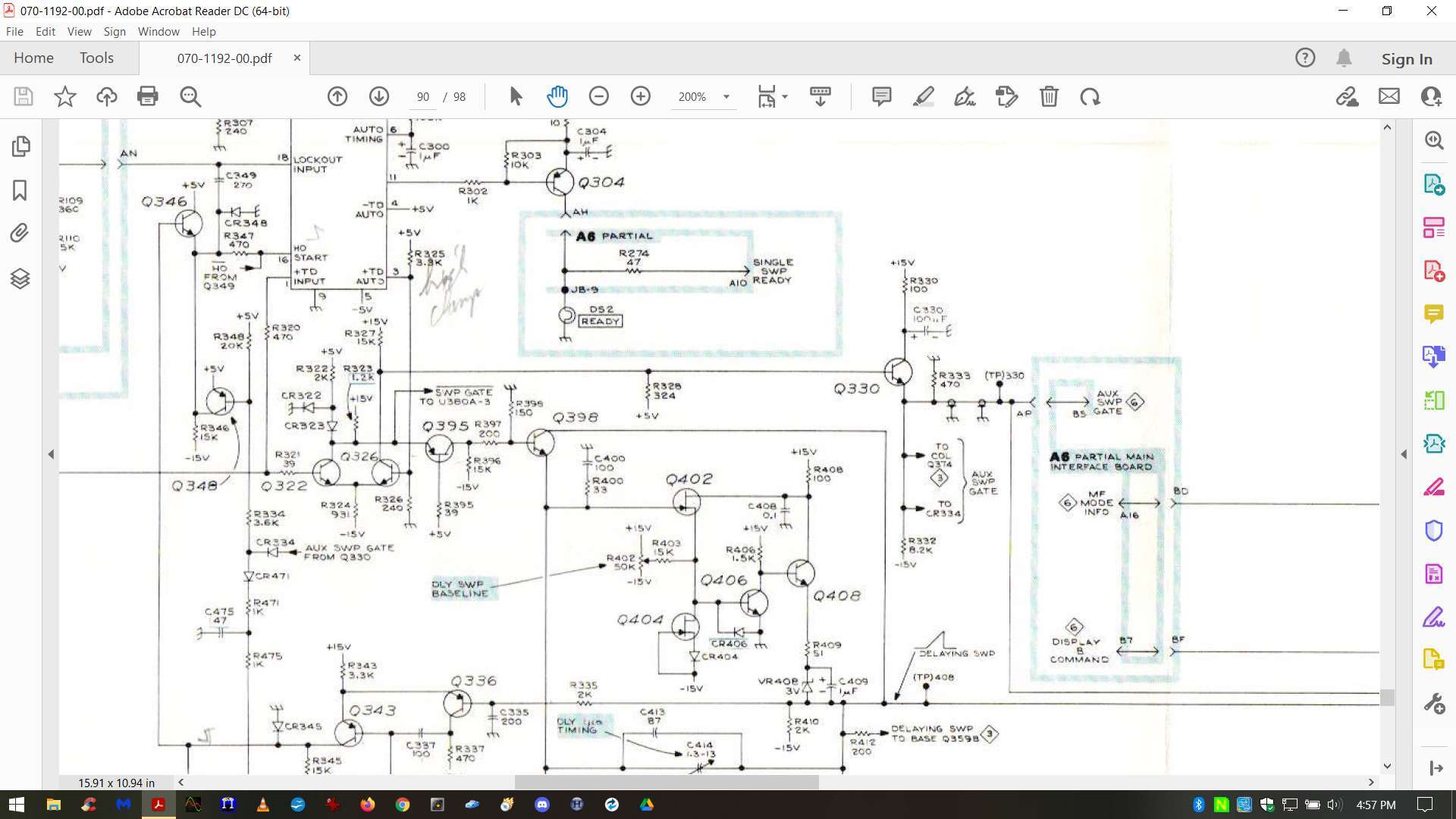
Started working on the 7B92 plug-in. Since it has no trigger, no sweep, and no trace I figure the issue is probably power related. And in looking it over the sweep/trigger board it is full of tants. Been a while since I've been on a tant hunt so let's get at it.
And sometimes the Tek gods grant you favors. C330, 100uf/20V, dead short. Didn't have exact value on hand so used a 47uf and 33uf in parallel. Should be good enough. Surprisingly that shorted tant did not burn up R330 (100 ohm). I also checked Q330 and it's OK. All the other tants are OK.
But I guess I didn't completely please the Tek gods. The plug-in still doesn't work. But there was some progress. Moving trigger control or time base will get the trace to flash and then disappear. So more troubleshooting needed. And that's going to be tough since I don't have a 7000 series plug-in extender. So I'll have to decide and think about how to proceed from this point.

-
So, just out of curiosity, I dug my old P-Touch out of the drawer unit in the garage; haven't touched it since I packed it in the trailer over 2 years ago. Didn't let it warm up from the cold nor nuthin'; just popped some batteries in it and put the boots to it. Will it work...?
I'd say that's a unqualified yes.
One thing I do prefer about this PT-80 is the keys; they're individual membrane keys separated by hard plastic bezel rather than a contiguous membrane matrix keypad like the ones above. They have a well-defined detent feel and each key doesn't feel "connected" to the rest of the keypad as those tend to feel. I also prefer the landscape orientation of the body, but that might just be due to familiarity.
mnem