-
https://youtu.be/Gn_-z-noVGs
That's some fab fabbing, mnem. Added to POI.
And now I've finally got a minute to post some pics... I went and did it just to prove I wasn't just blowing smoke up your arse.
As always... the fabricobbling comes easy; its documenting shit that makes it take 3 times as long.
For now I'm just going to leave this here with the descriptions on the photos... it's late & I'm tired, and I have the kids all over me like ferrets on crack until Monday. Oh, and a road trip to Louisiana in there somewhere I need to rest up for...
Thanks for the positive feedback guys!
This just came this afternoon... it's my next "phase" in the article. These are less than $10 anywhere, including Amazon with free next-day (how I bought it). What's interesting is that while it's an 80x25 size fan like the one I'm working with, it comes ready-made with 40CM leads, one of which is a remote thermal sensor!
It's also one of the new "super-quiet" fluid-bearing fans, and rated at 31CFM max flow.
We'll see how it works out...
mnem
*currently vacationing in Marwen*
-
That's a lot of damn caps... a few were leaking, most check okay, a few a bit week. This is the Boeschert power supply out of my second 53310a, caps on order.
You can see where the caps were leaking, but the board cleaned up nicely (not in this pic).
Woahh good job
Are you using one of those desoldering gun ? Two irons ? Or just a lot of patience ? -
That's a lot of damn caps... a few were leaking, most check okay, a few a bit week. This is the Boeschert power supply out of my second 53310a, caps on order.
You can see where the caps were leaking, but the board cleaned up nicely (not in this pic).
Woahh good job
Are you using one of those desoldering gun ? Two irons ? Or just a lot of patience ?
I'm old fashioned, solder wick and a weller wsl2
-
Solderwick (fresh) is very under-rated.
-
That's a lot of damn caps... a few were leaking, most check okay, a few a bit week. This is the Boeschert power supply out of my second 53310a, caps on order.
You can see where the caps were leaking, but the board cleaned up nicely (not in this pic).
Woahh good job
Are you using one of those desoldering gun ? Two irons ? Or just a lot of patience ?
I applied a the EEVblog and .edu discounts on tequipment to buy me a Hakko handheld desoldering gun last year and it is the best thing ever. I can imagine one of the bigger units with a separate vacuum unit is even better. I don't need it often, but when I do, it beats wick hands down. -
One of these days I'll buy a nice de-soldering station... One of these days...
-
Just found a very cool feature on my Racal 9915 counter. On the A input (40-520MHz) it has an AGC and a corresponding AGC output on the back of the unit.
So I was just building a frequency multiplier as I need a 30MHz source and only have 25MHz AWG (fail!). Easy enough - just shove a grounded emitter amp with a 30MHz tank on it (600nH + 22-ish pF) into the front of your 10MHz source (Rigol AWG). Well turns out if you plonk your DMM (or voltmeter) across the two AGC terminals on the back it'll allow you to get a rough signal strength indication. Pop it on the multiplier and tune for max value and job done! Very handy.
Damnit, yet another reason I can't get rid of my 9915!
For the unwary, note that the frequency adjustment on the back is not simply a plate that you can move between the coarse- and fine-adjust holes. No, it's the body of the OCXO; there is only one hole. Had to open it up again to put it back, and a couple more bits of hardware (a nut and washer) fell out. I'm not surprised--this one was difficult to get in to, with corroded/frozen screws to drill out. The battery worked once, too, but I daren't keep it charged right now. It's a bit fuzzy. -
The find of the evening came while we were sorting through boxes of printer switches, random power cords, etc: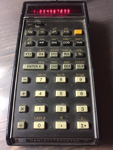
Damn if it didn't have the AC adapter still attached and lit up when I hit the power switch. Do you want it? I was just going to throw it in with a bunch of computers going to ecycle. I allowed as I would find it useful and set it aside.
An HP45! Yes, the very same model my vo-tech instructor used to flaunt while checking our (slide-rule-calculated) quiz and test answers. I haven't seen one in more than forty years. It cost 395USD in 1973 and was the first calculator to have a shift key
Happily, the battery (last changed in 1986) didn't leak. Tomorrow I will figure out how to build a replacement battery pack and put it back into daily use.
Calculator collecting is just as addicting as test equipment. See http://web.jlw.com/test/calc.html
While I no longer have an HP-45, I do have an HP-34C and an HP-97 from the next generation. -
I've been investing so much time sorting, researching, stacking, and inventorying stuff that I haven't been spending any time at my bench actually building or fixing anything and it was making me sort of, well, crabby. So I nixed the planned evening's project, went down to the garage and the first thing that came to hand was this:
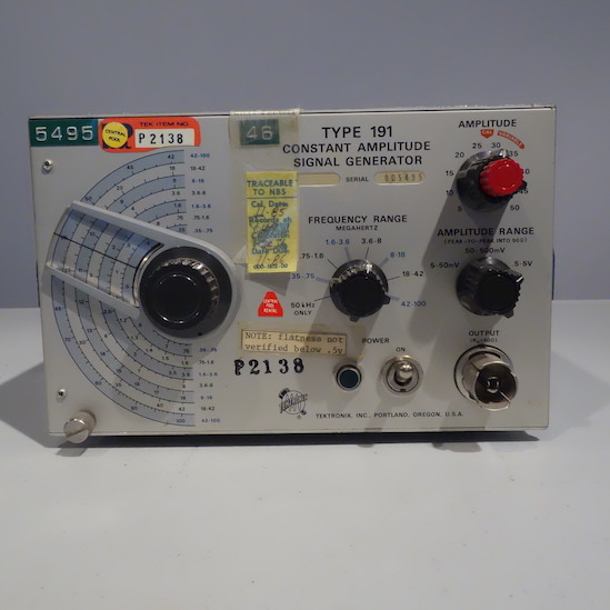
I had a power cord that would work once I removed the power cord condom. Did that, printed out the test section of the manual, pulled off the covers and did a visual inspection: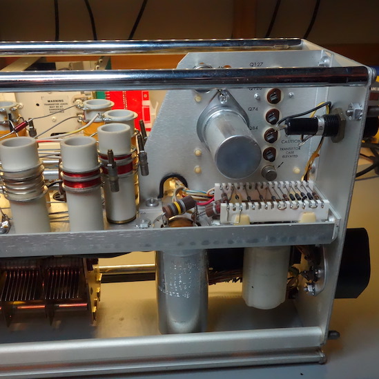
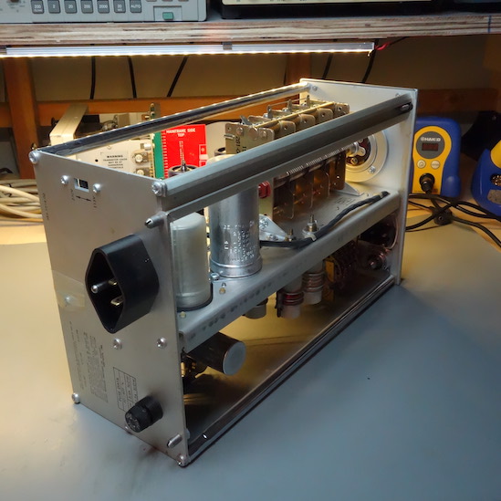
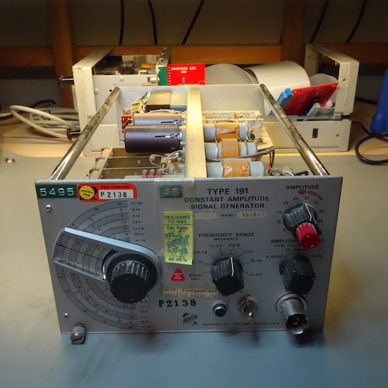
The inside was dusty but otherwise in good shape. No damaged tubes or capacitors. Lookit all that hollow state goodness. I decided to take a chance and power it up. No flashes or bangs and a lovely glow from the neon power light in the front panel. I checked the three DC voltages: -11VDC, +6.2VDC, and +450VDC. Suddenly I remembered why I decided to go into digital design back in 1978. The 11VDC and 6.2VDC rails were within a volt of spec, +450VDC within 2.5.
Pretty damn good, so I set it up for a middle of the dial frequency, set the output to 5 - 50mV and hooked up an oscilloscope.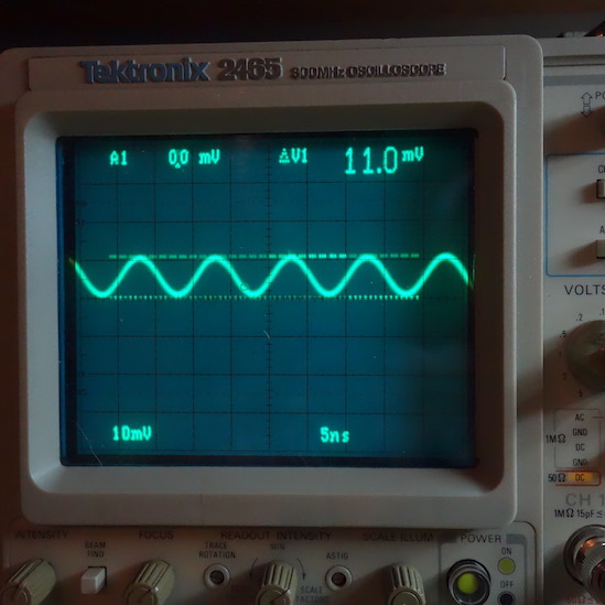
SINE WAVE!
I ran through the voltage output settings and looked at the output through the frequency range. All looked good. Finally, this: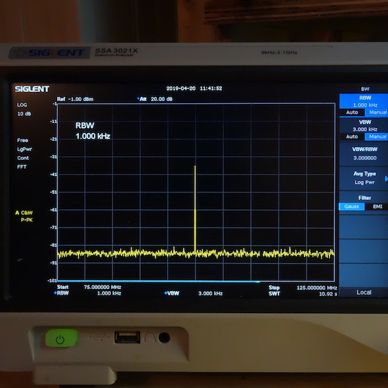
That's the output at 100MHz. Not too shabby for a piece of gear built around 1966 and last calibrated in 1984. Not wanting to press my luck, I turned it off and set it aside until I can do a more careful check of it and run through the full test and calibration procedure.
Just for fun, here's the schematic: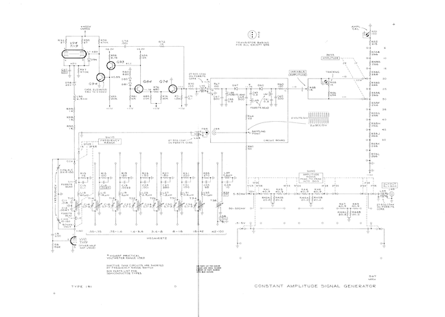
Which can be found here:
http://w140.com/tekwiki/wiki/191#/media/File:191.png
-
LOL - I have one of those 191s buried around here somewhere. I've no idea where, though - got it a few years ago at Apex in CA, the same day I saw those GR connectors in person for the first time earlier at a swap meet. Of course I didn't BUY any of them, as I had never before seen them, and had nothing that used them. Until a few hours later.


I need to get my act together and start running through this stuff.
-Pat -
Made good progress on running the 7904A. This is a hell of a scope. On the off chance does anyone know how to "zoom in" properly on a rising edge for a rise time measurement? On my 2465B I don't really have to think about it, but on the 7904A the edges always end up off the screen.
Looks like the 7A26 needs some compensation adjustments, especially channel 1 (see pics). Unfortunately I don't yet have all the specified things for the cal procedure from the 7A26 manual.
-
*stable* trace @ 1.1 GHz with the 7A19 amplifier. That's almost twice the rated b/w of the 7A19. Obviously, it's attenuated and not technically calibrated at 200 ps/div...and I need a lot of gain to see it, but that's damn impressive.
-
Open HV Probe - empty shell for 3D printing with room for commercially available 990 MOhm 40+kV resistor stack. (Ohmite $22 USD for 500, 400, 90) or whatever other guts people might want to fit.
Rough model over a Beer. 350mm total length so it is sort of a clone of other commercial products out there. Will be made in screw together sections with an M5 tip holder.
Thoughts welcome, time for a second Beer
-
Made good progress on running the 7904A. This is a hell of a scope. On the off chance does anyone know how to "zoom in" properly on a rising edge for a rise time measurement? On my 2465B I don't really have to think about it, but on the 7904A the edges always end up off the screen.
Looks like the 7A26 needs some compensation adjustments, especially channel 1 (see pics). Unfortunately I don't yet have all the specified things for the cal procedure from the 7A26 manual.
Go to the 5 mV setting first and check the trace. If it's peaking like that then the issue is NOT the compensation adjustments in the switch deck but the adjustments in the pre-amp section itself. The 5mV setting goes directly into the pre-amp and bypasses the switch deck compensation. If that trace is OK then proceed with the adjustments at the other switch sections. And be aware there will be interaction between switch settings. And typically on the attenuators a peak like that is corrected with the bottom adjustment. The top adjustment generally affects the flat top but again there is interaction. Work slowly and carefully and with each adjustment go back and check the other settings. Trust me. I've done a few including the 7A26. They can be a real PITA but worth the trouble.
Edit...also...in my experience you don't need the additional "compensator" and some the other expensive equipment to do a decent compensation. Just a fast rise time and high quality 1Khz square wave will get you there. And obviously it needs to have adjustable gain to do each deck. -
Made good progress on running the 7904A. This is a hell of a scope. On the off chance does anyone know how to "zoom in" properly on a rising edge for a rise time measurement? On my 2465B I don't really have to think about it, but on the 7904A the edges always end up off the screen.
Looks like the 7A26 needs some compensation adjustments, especially channel 1 (see pics). Unfortunately I don't yet have all the specified things for the cal procedure from the 7A26 manual.
Go to the 5 mV setting first and check the trace. If it's peaking like that then the issue is NOT the compensation adjustments in the switch deck but the adjustments in the pre-amp section itself. The 5mV setting goes directly into the pre-amp and bypasses the switch deck compensation. If that trace is OK then proceed with the adjustments at the other switch sections. And be aware there will be interaction between switch settings. And typically on the attenuators a peak like that is corrected with the bottom adjustment. The top adjustment generally affects the flat top but again there is interaction. Work slowly and carefully and with each adjustment go back and check the other settings. Trust me. I've done a few including the 7A26. They can be a real PITA but worth the trouble.
Edit...also...in my experience you don't need the additional "compensator" and some the other expensive equipment to do a decent compensation. Just a fast rise time and high quality 1Khz square wave will get you there. And obviously it needs to have adjustable gain to do each deck.
Thanks! See attached. Seems Ch 1 is fine up to 50 mV/div, then it starts overshooting.
-
Once to get to about 50mV at the 5mV switch setting you are going to start over loading the pre-amp. If it looks OK at say 20 or 30mV then you are golden. Proceed with the attenuator adjustments at the higher switch ranges.
-
Isn't that overshoot what we call Step Response ?
There should be instruction of how to trim it out against a suitably fast edge source.
RTFM.
-
I agree, I love mine, it saves so much time the only problem is having to change the nozzle from time to time [emoji16]That's a lot of damn caps... a few were leaking, most check okay, a few a bit week. This is the Boeschert power supply out of my second 53310a, caps on order.
You can see where the caps were leaking, but the board cleaned up nicely (not in this pic).
Woahh good job
Are you using one of those desoldering gun ? Two irons ? Or just a lot of patience ?
I applied a the EEVblog and .edu discounts on tequipment to buy me a Hakko handheld desoldering gun last year and it is the best thing ever. I can imagine one of the bigger units with a separate vacuum unit is even better. I don't need it often, but when I do, it beats wick hands down.
Sent from my POT-LX1 using Tapatalk
-
Isn't that overshoot what we call Step Response ?
There should be instruction of how to trim it out against a suitably fast edge source.
RTFM.
If it is "step response" Tek doesn't call it that. He just demonstrated with his last post that the pre-amp section is OK and should not require any adjustments. The issue is the attenuator adjustments in the switch deck. Yes, the manual tells you how to do it but I'm warning him that there is ALOT of interaction that the manual doesn't mention and can frustrate a "first timer"
-
Agreed, so to is watch collecting. [emoji16]
The find of the evening came while we were sorting through boxes of printer switches, random power cords, etc:
Damn if it didn't have the AC adapter still attached and lit up when I hit the power switch. Do you want it? I was just going to throw it in with a bunch of computers going to ecycle. I allowed as I would find it useful and set it aside.
An HP45! Yes, the very same model my vo-tech instructor used to flaunt while checking our (slide-rule-calculated) quiz and test answers. I haven't seen one in more than forty years. It cost 395USD in 1973 and was the first calculator to have a shift key
Happily, the battery (last changed in 1986) didn't leak. Tomorrow I will figure out how to build a replacement battery pack and put it back into daily use.
Calculator collecting is just as addicting as test equipment. See http://web.jlw.com/test/calc.html
While I no longer have an HP-45, I do have an HP-34C and an HP-97 from the next generation.
Sent from my POT-LX1 using Tapatalk
-
OK yeah, there's no overshoot on some V/div ranges which as you say points to individual attenuation adjustments.Isn't that overshoot what we call Step Response ?
There should be instruction of how to trim it out against a suitably fast edge source.
RTFM.
If it is "step response" Tek doesn't call it that. He just demonstrated with his last post that the pre-amp section is OK and should not require any adjustments. The issue is the attenuator adjustments in the switch deck. Yes, the manual tells you how to do it but I'm warning him that there is ALOT of interaction that the manual doesn't mention and can frustrate a "first timer"
Could just one be possibly damaged and affect a few others ? -
OK yeah, there's no overshoot on some V/div ranges which as you say points to individual attenuation adjustments.Isn't that overshoot what we call Step Response ?
There should be instruction of how to trim it out against a suitably fast edge source.
RTFM.
If it is "step response" Tek doesn't call it that. He just demonstrated with his last post that the pre-amp section is OK and should not require any adjustments. The issue is the attenuator adjustments in the switch deck. Yes, the manual tells you how to do it but I'm warning him that there is ALOT of interaction that the manual doesn't mention and can frustrate a "first timer"
Could just one be possibly damaged and affect a few others ?
Yes, there is some interaction between ranges which can catch you off guard. If you make an adjustment you basically have to go back and check everything again. It can be quite tricky.
-
Would you ever suspect one setting to have been damaged maybe with an over-voltage event ?
OK yeah, there's no overshoot on some V/div ranges which as you say points to individual attenuation adjustments.Isn't that overshoot what we call Step Response ?
There should be instruction of how to trim it out against a suitably fast edge source.
RTFM.
If it is "step response" Tek doesn't call it that. He just demonstrated with his last post that the pre-amp section is OK and should not require any adjustments. The issue is the attenuator adjustments in the switch deck. Yes, the manual tells you how to do it but I'm warning him that there is ALOT of interaction that the manual doesn't mention and can frustrate a "first timer"
Could just one be possibly damaged and affect a few others ?
Yes, there is some interaction between ranges which can catch you off guard. If you make an adjustment you basically have to go back and check everything again. It can be quite tricky.
If that was the case would you check to see which setting is most effected and then check the attenuator components for accuracy before attempting to trim it out ?
Or would such an event more likely damage something else in the inputs ? -
Would you ever suspect one setting to have been damaged maybe with an over-voltage event ?
OK yeah, there's no overshoot on some V/div ranges which as you say points to individual attenuation adjustments.Isn't that overshoot what we call Step Response ?
There should be instruction of how to trim it out against a suitably fast edge source.
RTFM.
If it is "step response" Tek doesn't call it that. He just demonstrated with his last post that the pre-amp section is OK and should not require any adjustments. The issue is the attenuator adjustments in the switch deck. Yes, the manual tells you how to do it but I'm warning him that there is ALOT of interaction that the manual doesn't mention and can frustrate a "first timer"
Could just one be possibly damaged and affect a few others ?
Yes, there is some interaction between ranges which can catch you off guard. If you make an adjustment you basically have to go back and check everything again. It can be quite tricky.
If that was the case would you check to see which setting is most effected and then check the attenuator components for accuracy before attempting to trim it out ?
Or would such an event more likely damage something else in the inputs ?
Yep, the attenuator blocks can get damaged by an overload event. Usually causes it to burn out and open up. That's one reason why I'm waiting on a 4x attenuator for a 465B. In trying to fix all the issues with it's channel 2 I discovered a partially open 4x attenuator. -
Also it appears that the thick film resistors can actually come off the substrate as well. Had one like that and no sign of burning or overload. Was just bubbly inside the attenuator module.
Edit: appears that Herpes are delivering my TF2015 signal generator today