Here's what I'm dealing with as far as the cracks in the PCB switch assembly. Stress cracks in the white plastic parts. This basically comes from decades of applied stress by the aluminum covers that snap onto these plastic parts.
So far, a test using gap filling (thicker) CA glue seems to be working. Need to treat all the cracks in both switches. I'm going to get this job out of the way first.
Hi Xrunner, you are here blazing the trail on which others might have to follow!
I'm not sure whether the usual proposal of cobbling together a 3d-print will satisfy the requirements of dimensional and positional accuracy here. And whether this is the case will not show immetiately but will affect the lifetime of the switches massively.
Maybe the enclosed document can help you:
If it is insufficient, I have more which would need to be mailed to you.
Hi Xrunner, you are here blazing the trail on which others might have to follow!
I'm not sure whether the usual proposal of cobbling together a 3d-print will satisfy the requirements of dimensional and positional accuracy here. And whether this is the case will not show immetiately but will affect the lifetime of the switches massively.
Maybe the enclosed document can help you:
If it is insufficient, I have more which would need to be mailed to you.
Thanks. I'm used to non-destructive testing so will have to think really hard about trying those thermal tests.

Hi Xrunner, you are here blazing the trail on which others might have to follow!
I'm not sure whether the usual proposal of cobbling together a 3d-print will satisfy the requirements of dimensional and positional accuracy here. And whether this is the case will not show immetiately but will affect the lifetime of the switches massively.
Maybe the enclosed document can help you:
If it is insufficient, I have more which would need to be mailed to you.
Thanks. I'm used to non-destructive testing so will have to think really hard about trying those thermal tests.
Well, the other document contains more varied methods, so if you do not make progress, send me a PM with your EM adress. I fear that I will have to go there too with the FG504 in due time. The phenomenon of repeated to-and-fro-switching being necessary for (continuously less likely) function in a certain range sounds familiar.
Well, the other document contains more varied methods, so if you do not make progress, send me a PM with your EM adress. I fear that I will have to go there too with the FG504 in due time. The phenomenon of repeated to-and-fro-switching being necessary for (continuously less likely) function in a certain range sounds familiar.
Old plastic is going to be the death of these things. I think this fix will be OK. The aluminum cover that snaps onto these plastic parts is just a dust cover - it has no electrical connection to ground. The problem is they are U-channel (it looks like) that is cut to length. Then they bent the "U" in a bit on both covers, so that they snap into place. This is the force that over 30 years has won out. But they really don't need to snap in that hard and I don't want my repair to break again.
What I'm going to do is un-bend the "U" (so that it's actually back in a "U" shape) so that it barely snaps into place. Another detail that keeps them on is the round nub at the top. It grips the cover as well so we don't need all that force going on at the sides. Then, before putting them on, I will apply a small drop of some non-permanent tacky glue on the top of the white plastic that will help prevent them from coming off.
That's all they need to do - just "be there" to keep dust out.

Well, the other document contains more varied methods, so if you do not make progress, send me a PM with your EM adress. I fear that I will have to go there too with the FG504 in due time. The phenomenon of repeated to-and-fro-switching being necessary for (continuously less likely) function in a certain range sounds familiar.
Old plastic is going to be the death of these things. I think this fix will be OK. The aluminum cover that snaps onto these plastic parts is just a dust cover - it has no electrical connection to ground. The problem is they are U-channel (it looks like) that is cut to length. Then they bent the "U" in a bit on both covers, so that they snap into place. This is the force that over 30 years has won out. But they really don't need to snap in that hard and I don't want my repair to break again.
What I'm going to do is un-bend the "U" (so that it's actually back in a "U" shape) so that it barely snaps into place. Another detail that keeps them on is the round nub at the top. It grips the cover as well so we don't need all that force going on at the sides. Then, before putting them on, I will apply a small drop of some non-permanent tacky glue on the top of the white plastic that will help prevent them from coming off.
That's all they need to do - just "be there" to keep dust out.
I was referring not to the cover, but the white plastic parts, which define the position of the cams in relation to the contacts, don't they?
I was referring not to the cover, but the white plastic parts, which define the position of the cams in relation to the contacts, don't they?
Yes they do. Can a 3D printed part be designed to replace them and function the same? I'm not sure it would be accurate enough. It would be a close call.
So after waiting for months for the panel mount USB connectors, it appear they are too big for my enclosure

I had to resort using one of those usb breakout board mounted on some spacers.
-group-therapy-thread/?action=dlattach;attach=1004374;image)
-group-therapy-thread/?action=dlattach;attach=1004376;image)
That was the last part I needed to finish my Jim Williams pulse generator. I ended up with 338ps rise time and a somehow squareish waveform which is not bad for an old transistor.
The nice labelling is a great idea from Wolfgang (mica paper, laser printer and spray adhesive)
-group-therapy-thread/?action=dlattach;attach=1004380;image)
The inside. The delay line is under the pulser.
-group-therapy-thread/?action=dlattach;attach=1004378;image)
This is really the best I could get. Playing with the grounds was interesting.
-group-therapy-thread/?action=dlattach;attach=1004382;image)
The rise time.
-group-therapy-thread/?action=dlattach;attach=1004384;image)
Next step is constructing one with a trigger input.
Very nice, Kosmic! Where'd you find that enclosure? Also nice job adding the delay line in to lengthen the pulse...I need to do that on my next prototype! Also, which LeCroy are you using? I've been eyeing DDA-120 due to the attractive price.
Very nice, Kosmic! Where'd you find that enclosure? Also nice job adding the delay line in to lengthen the pulse...I need to do that on my next prototype! Also, which LeCroy are you using? I've been eyeing DDA-120 due to the attractive price.
Enclosure is Hammond 1590A. They are really common should be easy to find.
The scope is a Lecroy DDA-260 (same as WavePro 960) I got some time ago
https://www.eevblog.com/forum/testgear/test-equipment-anonymous-(tea)-group-therapy-thread/msg2812236/#msg2812236I replaced most of the encoders, converted the LCD backlight to LED but still need to fix or 3d print that front panel

Ooof, that did get wrecked. thanks for the tips!

Been giving the Type 106 Square Wave Generator a good check out and have come up with a list of repairs required.
I thought at first the Fast Rise – Output was not working. It is indeed working. The issue is the GR connector. I need to take apart that complicated assembly to find out what's wrong with it. It's the top one in this pix.

The Bias Level pot (R39, 25K) is a very critical adjustment. Must be set exactly or the output looks like garbage or there's no output at all. The problem is the pot is very sloppy. So sensitive that just turning the unit over causes it to drift. And it's sealed so can't be cleaned/repaired. It will be replaced with a high quality Bourns pot.
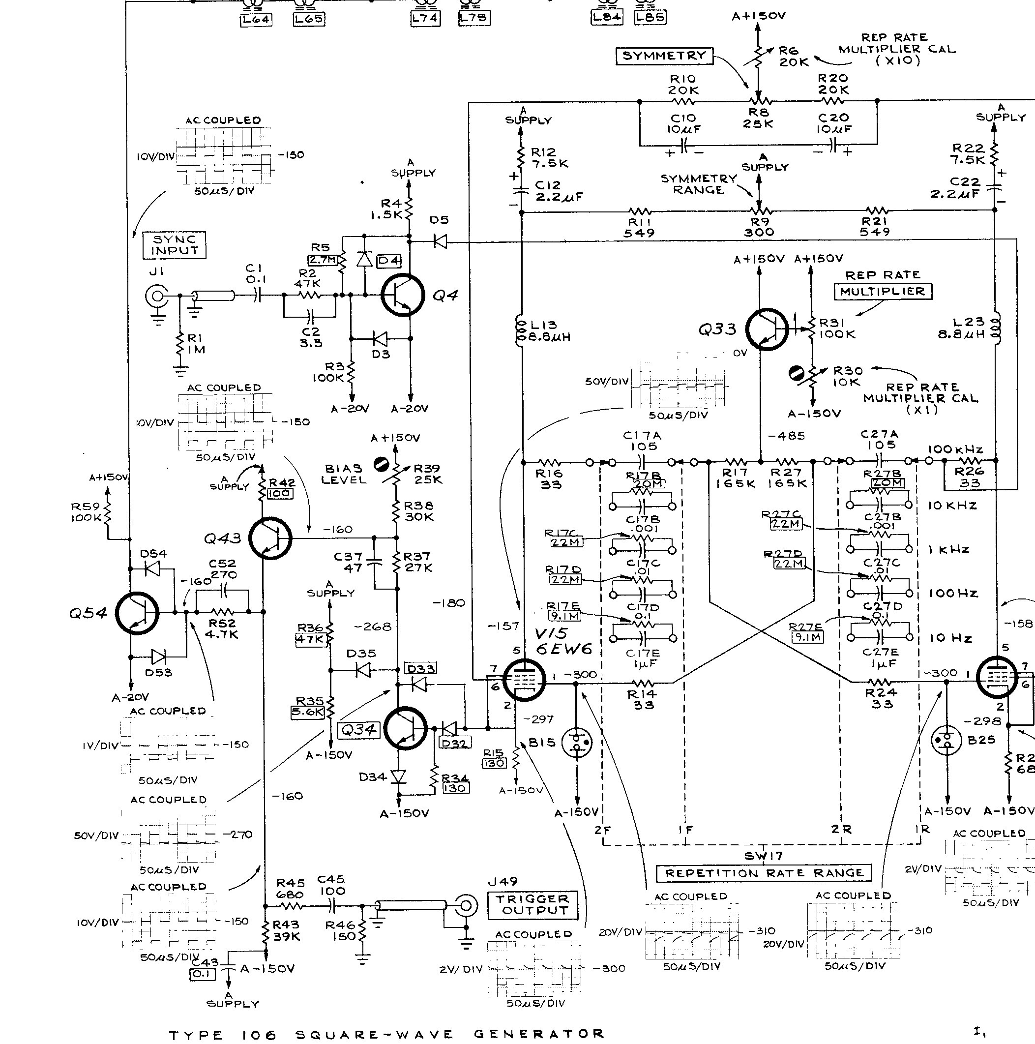
Re-capping this unit is going to be a lengthy (and expensive) process so I'm going to do it in stages. Of all the PSU voltages the +150V is the farthest from nominal at +144V so that will get attention first. And just by coincidence it supplies the critical bias circuit. The 3 x 20uf/350V will be replaced by a single 68uf/350V. I'm also going to replace D255 (150V/5W zener) and C255. The zener is a 1N5383 and is still available. At this point I'm not going to replace Q257 which is an obsolete 2N3441 in a TO-66 package unless the output is still too low. Luckily an NTE175 in a TO-66 package is a direct cross.
At the same time I'll also re-cap the “A Supply” plus the numerous small value axial electrolytics scattered through out the unit. The balance of the PSU will be re-capped at a later date.


Very nice, Kosmic! Where'd you find that enclosure? Also nice job adding the delay line in to lengthen the pulse...I need to do that on my next prototype! Also, which LeCroy are you using? I've been eyeing DDA-120 due to the attractive price.
Enclosure is Hammond 1590A. They are really common should be easy to find.
The scope is a Lecroy DDA-260 (same as WavePro 960) I got some time ago https://www.eevblog.com/forum/testgear/test-equipment-anonymous-(tea)-group-therapy-thread/msg2812236/#msg2812236
I replaced most of the encoders, converted the LCD backlight to LED but still need to fix or 3d print that front panel
The main reason I've been considering a 3D printer is to be able to print LeCroy front panels

I just bought a 3d printer to print such kind of part but currently I'm hardly struggling to adjust the printer to the printing quality
On this date in 1973 a bright eyed and enthusiastic 19 year old (turned 20 on the 27th) fresh out of technical college started his long and usually fulfilling career in the corporate world.
On 31st May 2009 that same corporate entity decided that his skills and talents were "surplus" and forced an early retirement.
Am I bitter about it? I was at the time. But I worked for them as a contractor for 10 more years and those 10 years were more enjoyable and fulfilling than the last 10 years I was employed directly by them.
Congratulations on mugging the bastards back as a contractor

Congratulations on mugging the bastards back as a contractor
Well the pay wasn't exactly stellar but I had no responsibility other than test the mainframe and go home and not give it a 2nd thought. The regular employees had that plus all the other corporate bullshit responsibilities that went along with it.

On this date in 1973 a bright eyed and enthusiastic 19 year old (turned 20 on the 27th) fresh out of technical college started his long and usually fulfilling career in the corporate world.
So a mere 24.5 kilodays old? From the grumpyness levels I'd guessed at least 30k days.
Worst pregnancy ever! I'm imagining a Mr Burns foetus passing caustic memos out through the cervix: "Smithers - Fire housekeeping! It's a mess in here".
Been giving the Type 106 Square Wave Generator a good check out and have come up with a list of repairs required.
I thought at first the Fast Rise – Output was not working. It is indeed working. The issue is the GR connector. I need to take apart that complicated assembly to find out what's wrong with it. It's the top one in this pix.
The Bias Level pot (R39, 25K) is a very critical adjustment. Must be set exactly or the output looks like garbage or there's no output at all. The problem is the pot is very sloppy. So sensitive that just turning the unit over causes it to drift. And it's sealed so can't be cleaned/repaired. It will be replaced with a high quality Bourns pot....
Since that board is relatively easy to remove, you might try dropping the pot (or even the entire PCB) in a glass full of alcohol (see my post on alcohol being still available as methyl hydrate) to see if alcohol can infiltrate enough to do the cleaning needed.
Keep the faith brother!
mnem
*currently checking the tracking on my new RC transmitter*


